

This is the 5V variant of the ESP8266 WiFi 5V 1 Channel Relay Module in Relay Modules. Available at ₹224.20 (₹190.00 + GST) with free shipping across India.
Description:
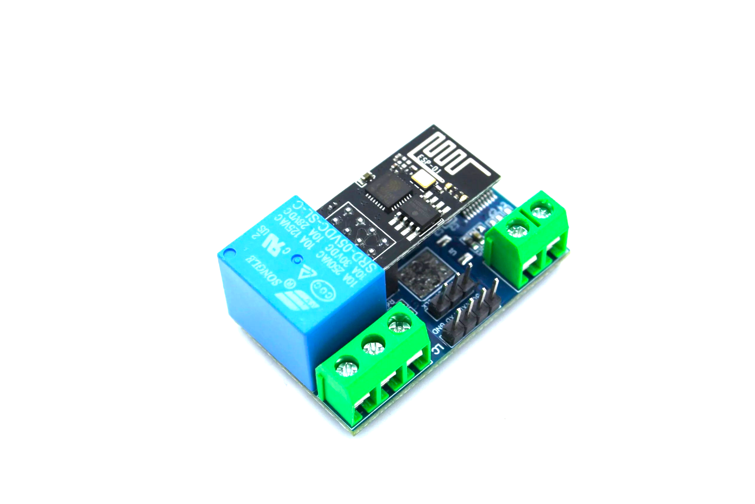
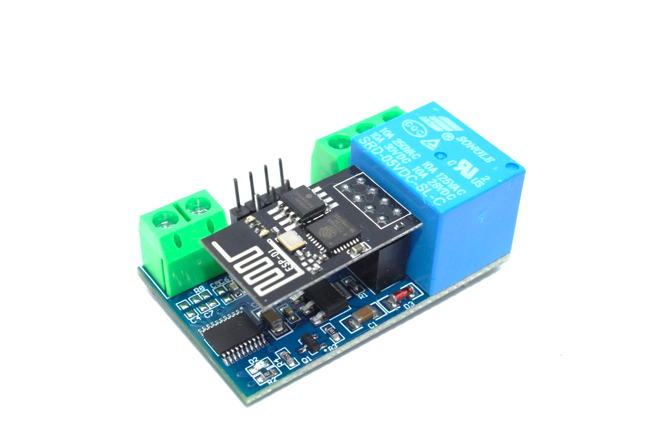
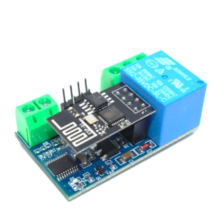
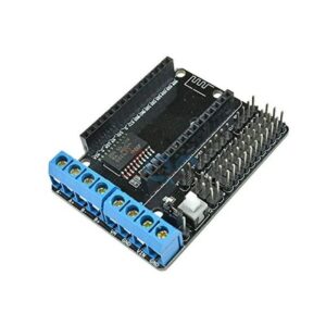
The ESP8266 WiFi 5V 1 Channel Relay Module is equipped with an ESP8266 WiFi module and microcontrollers, allowing for wireless control of the relay via a mobile app within a local area network (LAN). This onboard relay supports 5V, 10A / 250V AC and 10A / 30V DC, capable of enduring up to 10 million cycles, featuring overload protection and a fast response time.
How to Use:
The onboard ESP8266 WiFi module offers three operating modes:
- STA (client)
- AP (hotspot)
- STA + AP (client + hotspot)
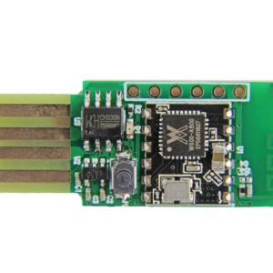
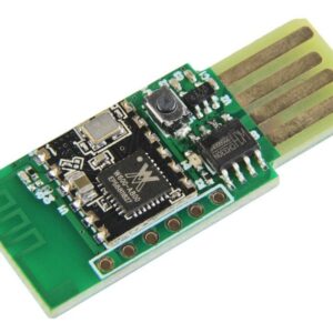
Select the appropriate mode based on your application. To configure the WiFi module, use serial debugging software on your computer along with a USB to TTL module to send AT commands.
Connect the USB to TTL module’s RX, TX, and GND pins to the corresponding TX, RX, and GND pins on the relay module, and provide a 5V power supply to the IN+ and IN– pins.
Note: This product is available in 2 relay module types:
- JQC3F-5VDC-C
- SRD-05VDC-SL-C
(It will be shipped randomly.)
General Info:
- Onboard ESP8266 WIFI module, AP mode can be connected at the same time 5 clients
- The module has two ways to work:
(i) Mobile phone directly mounted on the WIFI module
(ii) Mobile phone and WIFI module also carried on the router - Transmission distance:
- Open environment: The mobile phone mounted on the WIFI module when the maximum transmission distance is 400m
- When the WiFi module and mobile phone are carried on the router: transmission distance depends on the router’s signal strength
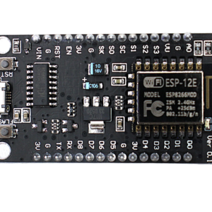
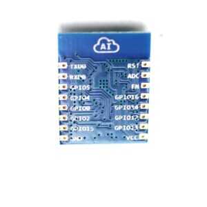
Board function description:
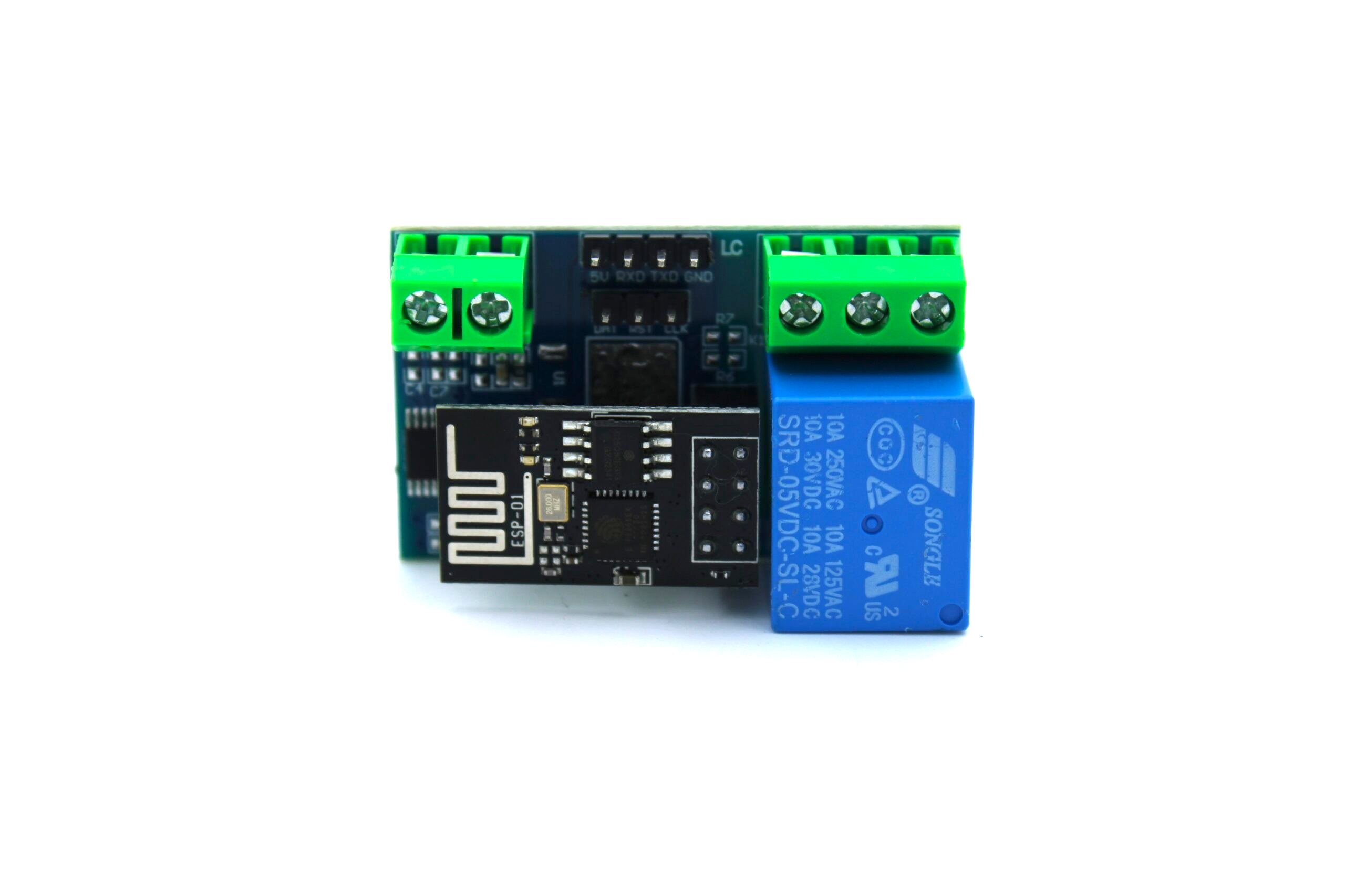
- IN +, IN-: 5V power input
- TX, RX, GND: Serial debug pin

The onboard ESP8266 WiFi module offers three operational modes:
-
STA (client)
-
AP (hotspot)
-
STA + AP (client + hotspot)
Depending on the intended use of the module, you should select the appropriate WiFi operating mode. Before using the module, configure it by sending serial commands via serial debugging software and a USB to TTL module.
It’s important to ensure that the module remains powered on after configuration, as some WiFi parameters may not be saved if power is lost. Once a network connection is established between your mobile phone and the WiFi module, you can use a mobile app to control the relay.
Control Commands:
When a cell phone equipped with WiFi module sends commands in the following order:
(The default baud rate is 115200)
- AT+CWMODE=2, namely AP mode is selected.
- AT+RST, reset.
- AT+CIPMUX=1, open multiple connections.
- AT+CIPSERVER=1,8080, configure the TCP server, set the port.
- AT+CIOBAUD=9600, set the baud rate to 9600 (working in relays to control the baud rate 9600).
- AT+CIFSR, to view the AP mode IP address, such as the APIP, “192.168.4.1”.
- Cell phone WiFi signal connection name starts with AI-THINKER or ESP8266.
- In the “TCP connection” address and port, enter the APP, such as 192.168.4.1 and 8080.
- Click on the grey box in the app to control the relay.
Features:
- Onboard Module: ESP8266 WiFi module; in AP mode it can connect with 5 Clients at the same time
- Operating Way:
- Cellphone connected directly to the WiFi module
- Cellphone and WiFi module connected to the same router, and use the APP to control relay
- Diode effusion protection
- Short response time
Specification:
| Model Type: | Relay Module |
|---|---|
| No. of Channels: | 1 |
| Transmission Distance | 400m (max) |
| Trigger Voltage (VDC) | 5 |
| Switching Voltage (VAC) | 250@10A |
| Switching Voltage (VDC) | 30@10A |
| Baud Rate (bps) | 9600 |
| Length (mm): | 45 |
| Width (mm): | 28 |
| Height (mm): | 20 |
Package Includes:
- 1 x ESP8266 WiFi 5V 1 Channel Relay Module
Attachments:

Smart Temple IoT: Crowd Monitoring and Donation Counter
Table of Contents IoT for Religious Institutions Crowd Monitoring and Safety Digital Donation Counter Environment and Heritage Preservation...
Read More →
ESP32 UART Serial: Reading GPS and GSM with Hardware Serial
Mastering ESP32 UART serial GPS GSM hardware serial communication is one of the most valuable skills for any...
Read More →
Smart Irrigation System with ESP32: Auto Watering Plants
A smart irrigation system with ESP32 is one of the most impactful IoT projects you can build for...
Read More →Technical Specifications
| Model | ESP8266 |
|---|---|
| Operating Voltage | 5V |
| Channels | 1-channel |
| Interface / Protocol | WiFi |
| SKU | AI0352 |
| Weight | 0.03 kg |
| Availability | Out of Stock |
Applications & Use Cases
The ESP8266 WiFi 5V 1 Channel Relay Module is a versatile relay modules used across a wide range of applications including home automation, industrial control, IoT projects, Arduino/Raspberry Pi interfacing, and motor control.
Common use cases:
- Switching high-voltage AC appliances with a microcontroller
- Building a smart home relay board
- Automating irrigation pumps in agriculture
This product is ideal for electronics engineers, IoT developers, and automation hobbyists.
Technical Tip: Use optocoupler-isolated relay modules to protect your microcontroller. Match relay coil voltage to your MCU logic level (3.3V or 5V).
Shipping & Delivery
- Free shipping on orders above ₹999 across India
- Dispatched within 1-3 business days
- Expected delivery: 3-7 business days depending on location
- Secure packaging to ensure safe transit of electronic components


Manoj Modi –
Excellent ESP8266 WiFi 5V 1 Channel Relay! WiFi connectivity is strong and stable. Perfect for IoT projects.
Hitesh Jain –
Great quality ESP8266 WiFi 5V 1 Channel Relay. Flashed with ESPHome and it works beautifully.
Gaurav Bose (verified owner) –
This ESP8266 WiFi 5V 1 Channel Relay is a beast for the price. Running a web server on it with no issues.
Karan Gill (verified owner) –
Nice ESP8266 WiFi 5V 1 Channel Relay for IoT prototyping. Breadboard compatible which is a plus.
Zubin Sethi (verified owner) –
Outstanding ESP8266 WiFi 5V 1 Channel Relay! Programmed it with Arduino IDE. All features work as documented.
Darshan Kohli (verified owner) –
Excellent for smart home projects. This ESP8266 WiFi 5V 1 Channel Relay connects reliably to my router.
Hardik Chatterjee (verified owner) –
Decent ESP8266 WiFi 5V 1 Channel Relay. Had to install CP2102 drivers but works fine after that.
Dinesh Rawat (verified owner) –
Decent ESP8266 WiFi 5V 1 Channel Relay. Had to install CP2102 drivers but works fine after that.
Hemant Bhatt –
Outstanding ESP8266 WiFi 5V 1 Channel Relay! Programmed it with Arduino IDE. All features work as documented.
Neha Negi (verified owner) –
Great quality ESP8266 WiFi 5V 1 Channel Relay. Flashed with ESPHome and it works beautifully.
Himanshu Batra –
Perfect for my IoT project. This ESP8266 WiFi 5V 1 Channel Relay has excellent WiFi performance.
Anil Goyal –
Love this ESP8266 WiFi 5V 1 Channel Relay. Built a smart switch with it. Works with Home Assistant perfectly.
Aarav Chopra (verified owner) –
Superb ESP8266 WiFi 5V 1 Channel Relay! Using it for my weather monitoring station. WiFi range is impressive.
Ajay Batra (verified owner) –
Excellent for smart home projects. This ESP8266 WiFi 5V 1 Channel Relay connects reliably to my router.
Anil Vohra (verified owner) –
Superb ESP8266 WiFi 5V 1 Channel Relay! Using it for my weather monitoring station. WiFi range is impressive.
Aarav Choudhury (verified owner) –
Perfect for my IoT project. This ESP8266 WiFi 5V 1 Channel Relay has excellent WiFi performance.
Aditya Agarwal (verified owner) –
Outstanding ESP8266 WiFi 5V 1 Channel Relay! Programmed it with Arduino IDE. All features work as documented.
Tanvi Pillai (verified owner) –
Outstanding ESP8266 WiFi 5V 1 Channel Relay! Programmed it with Arduino IDE. All features work as documented.
Chetan Dhillon (verified owner) –
This ESP8266 WiFi 5V 1 Channel Relay is amazing for home automation. Connected all my smart devices easily.
Naman Khurana (verified owner) –
This ESP8266 WiFi 5V 1 Channel Relay is amazing for home automation. Connected all my smart devices easily.
Arjun Saxena (verified owner) –
This ESP8266 WiFi 5V 1 Channel Relay is a beast for the price. Running a web server on it with no issues.
Anand Sharma (verified owner) –
Great quality ESP8266 WiFi 5V 1 Channel Relay. Flashed with ESPHome and it works beautifully.
Rohit Tandon (verified owner) –
Okay ESP8266 WiFi 5V 1 Channel Relay. Took time to figure out the pin mapping but functional.
Isha Menon (verified owner) –
Outstanding ESP8266 WiFi 5V 1 Channel Relay! Programmed it with Arduino IDE. All features work as documented.
Lakshmi Negi –
Superb ESP8266 WiFi 5V 1 Channel Relay! Using it for my weather monitoring station. WiFi range is impressive.
Abhishek Sharma (verified owner) –
This ESP8266 WiFi 5V 1 Channel Relay is amazing for home automation. Connected all my smart devices easily.