
Building an ESP32 deep sleep low power IoT sensor node is one of the most rewarding projects for any electronics enthusiast in India. Whether you want to monitor soil moisture in your farm, track temperature in a cold chain warehouse, or build a remote weather station in a location without mains power, the ESP32’s deep sleep capability can keep your device running for months — even years — on a single set of batteries. In this comprehensive guide, we’ll walk through everything you need to know: from understanding ESP32 sleep modes to wiring sensors, writing firmware, and optimising battery life for real Indian deployment scenarios.
Why Deep Sleep Matters for Battery-Powered IoT
The ESP32 is an exceptionally capable microcontroller, packing dual-core processing, Wi-Fi, Bluetooth, and dozens of peripherals into a tiny package. However, when fully active, it can draw anywhere between 160 mA to 260 mA — far too much for battery-powered applications. A standard 2000 mAh 18650 lithium cell would be drained in less than 15 hours if the ESP32 ran continuously at full power.
Deep sleep changes everything. In deep sleep mode, the ESP32 shuts down the CPU cores, Wi-Fi radio, Bluetooth stack, and most peripherals, retaining only the Real-Time Clock (RTC) subsystem and a tiny amount of RTC memory. Power consumption drops to roughly 5–10 µA (microamperes) — that’s about 20,000 times less than active mode. With the right design, a sensor node can wake up every 15 minutes, take a reading, transmit data over Wi-Fi, and go back to sleep — all within two seconds of active time — and run for well over a year on a single 18650 cell.
For Indian deployments specifically, this matters even more. Solar charging in rural areas, remote agricultural monitoring, cold chain logistics across vast distances, and smart building projects all demand devices that can operate independently for extended periods. Deep sleep is not a luxury; it is a fundamental design requirement.
ESP32 Sleep Modes Explained
Understanding the different sleep modes available in the ESP32 helps you make the right architectural decision for your project.
Light Sleep
In light sleep, the CPU is paused and clocks are gated, but RAM is retained and the Wi-Fi connection can be maintained. Current draw is around 0.8–1 mA. This mode is useful if you need very fast wake times (microseconds) and want to keep your Wi-Fi association alive, but it consumes far too much power for multi-month battery operation.
Deep Sleep
Deep sleep shuts down the CPU, Wi-Fi, Bluetooth, and most peripherals. Only the RTC controller, RTC peripherals (including the ultra-low-power ULP co-processor), and RTC memory remain powered. Wake-up time is around 300 µs to 1 ms. Current draw: approximately 5–10 µA depending on the oscillator and RTC peripheral configuration. This is the mode you’ll use for most battery-powered sensor nodes.
Hibernate Mode
Hibernate mode disables even more sub-systems including the slow RTC oscillator. Only the RTC timer using an external 32 kHz crystal can wake the device. Current draw can be as low as 2.5 µA. However, RTC memory content is lost and the only supported wake-up source is the timer. Use this when you need absolute minimum power and don’t need RTC memory persistence.
Wake-Up Sources
- Timer: Wake after a fixed duration using the internal RTC timer. Most common for periodic sensing.
- EXT0: Wake on a specific GPIO going high or low (single GPIO, GPIO 0–39).
- EXT1: Wake when one or more GPIOs change state (multiple GPIOs via RTC GPIOs only).
- Touch pad: Wake via capacitive touch on supported GPIO pins.
- ULP co-processor: The ultra-low-power RISC-V or FSM co-processor can sample sensors and wake the main CPU only when a threshold is crossed.
Hardware Build: Components and Wiring
For this tutorial, we’ll build a temperature, humidity, and barometric pressure sensor node that wakes every 10 minutes, reads sensors, connects to Wi-Fi, publishes data via MQTT, and returns to deep sleep.
Components Required
- ESP32 development board (30-pin variant recommended for its compact size)
- DHT20 or BME280 sensor (I2C interface, very low standby current)
- 18650 lithium battery x2 with battery shield
- 100 µF capacitor (for power supply decoupling during Wi-Fi bursts)
- 10 kΩ pull-up resistors for I2C lines (if not onboard)
- Optional: 5V/1W solar panel + TP4056 charging module for outdoor deployments

DHT20 SIP Packaged Temperature and Humidity Sensor
The DHT20 uses I2C and has a very low standby current, making it perfect for deep-sleep sensor nodes. More accurate and easier to wire than the older DHT11.

GY-BME280-3.3 Precision Altimeter Atmospheric Pressure Sensor Module
The BME280 measures temperature, humidity, and barometric pressure over I2C with very low power draw — ideal for weather monitoring sensor nodes running on battery.

2 x 18650 Lithium Battery Shield for Arduino/ESP32/ESP8266
A dual 18650 battery shield that provides stable 5V/3V output for the ESP32 and sensors, with USB charging support — excellent for portable or outdoor deployments.
Wiring
Connect the BME280 as follows: VCC → 3.3V, GND → GND, SDA → GPIO 21, SCL → GPIO 22. These are the default I2C pins on most ESP32 development boards. Power the entire assembly from the 3.3V rail of the battery shield to avoid the extra 100–200 mA quiescent current drawn by the onboard 5V regulator when running the ESP32 from 5V.
Important: Add a 100 µF electrolytic capacitor between 3.3V and GND close to the ESP32. During Wi-Fi transmission, the ESP32 draws current spikes of up to 350 mA that can cause voltage dips and brownout resets if the supply is not well-decoupled.
Writing the Firmware: Arduino IDE Deep Sleep Code
Below is a complete, production-ready Arduino sketch for our deep sleep sensor node. This covers Wi-Fi connection with a saved SSID/password, sensor reading, MQTT publishing, and entering deep sleep with a timer wake-up.
#include <WiFi.h>
#include <PubSubClient.h>
#include <Adafruit_BME280.h>

// ─── Configuration ─────────────────────────────────────
const char* SSID        = "YourWiFi";
const char* PASSWORD    = "YourPassword";
const char* MQTT_SERVER = "192.168.1.100";
const int   MQTT_PORT   = 1883;
const char* MQTT_TOPIC  = "home/sensor/node1";

// Sleep 10 minutes (600 seconds)
#define SLEEP_SECONDS 600
#define uS_TO_S       1000000ULL
// ────────────────────────────────────────────────────────

Adafruit_BME280 bme;
WiFiClient      espClient;
PubSubClient    mqttClient(espClient);

void connectWiFi() {
  WiFi.begin(SSID, PASSWORD);
  uint8_t attempts = 0;
  while (WiFi.status() != WL_CONNECTED && attempts < 20) {
    delay(500);
    attempts++;
  }
}

void setup() {
  Serial.begin(115200);
  Wire.begin(21, 22);

  if (!bme.begin(0x76)) {
    Serial.println("BME280 not found!");
  }

  connectWiFi();

  if (WiFi.status() == WL_CONNECTED) {
    mqttClient.setServer(MQTT_SERVER, MQTT_PORT);
    if (mqttClient.connect("esp32-node1")) {
      float temp = bme.readTemperature();
      float hum  = bme.readHumidity();
      float pres = bme.readPressure() / 100.0F;

      char payload[128];
      snprintf(payload, sizeof(payload),
        "{"temp":%.2f,"hum":%.2f,"pres":%.2f}",
        temp, hum, pres);

      mqttClient.publish(MQTT_TOPIC, payload);
      mqttClient.loop();
    }
  }

  WiFi.disconnect(true);
  WiFi.mode(WIFI_OFF);

  esp_sleep_enable_timer_wakeup(SLEEP_SECONDS * uS_TO_S);
  esp_deep_sleep_start();
}

void loop() {
  // Never reached in deep sleep mode
}
Key points about this code: We call WiFi.disconnect(true) and WiFi.mode(WIFI_OFF) before entering deep sleep. This ensures the Wi-Fi radio is fully powered down. Without this, some ESP32 boards can draw a few extra milliamps during sleep due to residual radio state. We also avoid delay() in the main flow — everything completes before sleep is triggered.
Saving Wi-Fi Credentials to RTC Memory
Every time the ESP32 wakes from deep sleep, it has to re-scan and re-connect to Wi-Fi, which can take 2–4 seconds. You can reduce this by storing the BSSID and channel number in RTC memory and using WiFi.begin(ssid, password, channel, bssid, true) on subsequent wakes. This typically cuts connection time to under 500 ms, saving significant energy.
Advanced Power Optimisation Techniques
1. Reduce Wi-Fi Connection Time
Wi-Fi is the single biggest power consumer in a deep sleep cycle. A 3-second connection at 150 mA consumes 0.125 mAh. Over 10,000 wake cycles (roughly one year at 10-minute intervals), that adds up to 1,250 mAh — more than half a 2000 mAh battery just for connecting. Strategies to reduce this:
- Store BSSID and channel in RTC memory as described above.
- Use a static IP address instead of DHCP — this alone can save 500 ms to 1 second per connection.
- Place the router/access point physically close to the sensor node or use a dedicated IoT access point on 2.4 GHz only.
2. Power Gate External Peripherals
Sensors like the BME280 have a standby current of only a few µA, but some sensors (ultrasonic modules, certain gas sensors, display modules) can draw several milliamps even when idle. Connect their VCC pin through a GPIO-controlled MOSFET so they are completely unpowered during deep sleep. Use a P-channel MOSFET (e.g., AO3407) driven from a GPIO pin — set the GPIO LOW to power the sensor, HIGH to cut power.
3. Avoid the Onboard LED and USB-to-UART Chip
Many development boards include a power LED and a USB-to-UART chip (e.g., CH340 or CP2102). These can draw 1–5 mA continuously. For production deployments, use a bare ESP32 module or desolder the LEDs. The 30-pin ESP32 expansion board from Zbotic is a good middle ground for prototyping without too much extra circuitry.
4. Use the ULP Co-processor for Sensor Polling
The ESP32’s ultra-low-power (ULP) co-processor runs independently of the main CPU at around 10–150 µA. You can program the ULP to read a simple sensor (e.g., an ADC value from a soil moisture sensor) and only wake the main CPU when a threshold is breached. This is an advanced technique but can extend battery life dramatically when most wake cycles would result in no-change readings.
5. Power Budget Calculation
Let’s calculate the expected battery life for our node:
- Active time per cycle: ~2 seconds at 150 mA average = 0.083 mAh
- Deep sleep time per cycle: ~598 seconds at 8 µA = 0.00133 mAh
- Total per cycle: ~0.085 mAh
- Cycles per day: 144 (every 10 minutes)
- Daily consumption: ~12.2 mAh
- Two 18650 cells (3,600 mAh combined, usable ~3,000 mAh): ~245 days (~8 months)
With a small 5V/1W solar panel charging via a TP4056 module, this setup can run indefinitely even in partially overcast Indian weather.
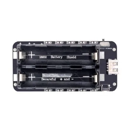
2 x 18650 Lithium Battery Shield V8 – 5V/3A, Micro USB
This V8 battery shield supports simultaneous charging and discharging, making it perfect for solar-assisted IoT sensor nodes deployed outdoors.
Real-World Deployment Tips for India
India presents unique deployment challenges that hobbyists and engineers must account for when building long-running IoT nodes.
Weatherproofing
India’s climate ranges from extreme humidity in coastal regions to extreme heat in the Deccan and Rajasthan. Use an IP65-rated enclosure for outdoor deployments. Apply conformal coating (available from electronics stores) to the PCB to protect against condensation. The DHT20 and BME280 are rated for operation up to 85°C, which is sufficient for most Indian conditions including direct-sun enclosures.
Wi-Fi Reliability
In rural areas, the Wi-Fi signal may be weak. Consider using an ESP32 with an external antenna connector (IPEX version) and attaching a 2.4 GHz omnidirectional antenna. Alternatively, use LoRa (SX1278) for the radio link and reserve Wi-Fi only for the gateway node — a much more power-efficient architecture for large farm deployments.
Power Supply for Agricultural Use
In agricultural settings far from mains power, the 4 x 18650 battery shield with a solar panel is a proven combination. Size the panel for at least 3x the daily consumption to account for cloudy monsoon days. A 2W panel paired with four 18650 cells (~7,200 mAh) will comfortably run our sensor node through even a week of zero sunlight.
OTA Firmware Updates
Plan for over-the-air (OTA) firmware updates from the start. Store a firmware version number in RTC memory and check for updates once per day (or once per N wake cycles). ArduinoOTA and the ESP-IDF OTA system both work well. This is critical because visiting each node physically to update firmware is impractical once you have dozens of nodes deployed.
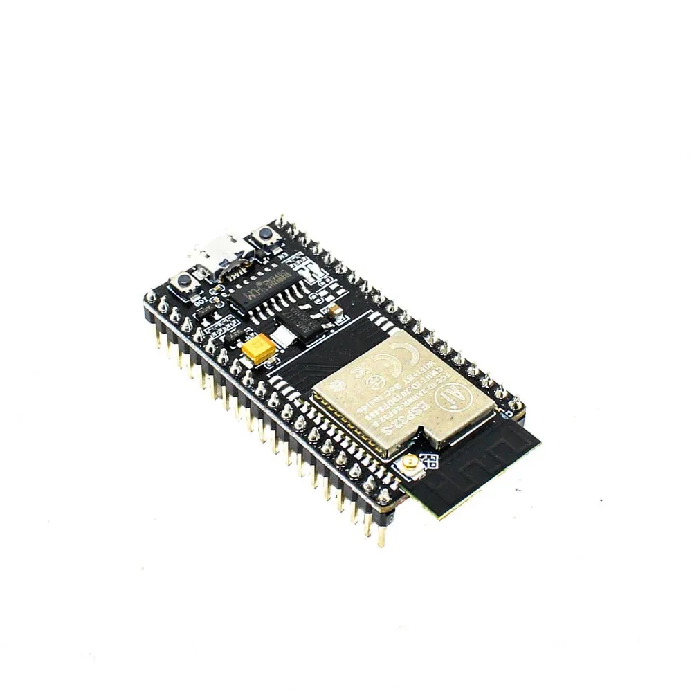
Ai Thinker NodeMCU-32S ESP32 Development Board – IPEX Version
This IPEX-antenna version allows you to attach an external antenna for improved Wi-Fi range in rural or large-area deployments — essential for farm IoT projects.
Frequently Asked Questions
What is the minimum current draw of the ESP32 in deep sleep?
With the RTC timer as the only wake source and no RTC peripherals active, the ESP32 draws approximately 5 µA in deep sleep. In hibernate mode (using an external 32 kHz crystal), this can drop to around 2.5 µA. In practice, most development boards with onboard voltage regulators and LEDs will draw more — typically 15–50 µA total.
Can the ESP32 retain data across deep sleep cycles?
Yes. The ESP32 has 8 KB of RTC memory that retains its contents through deep sleep. You can declare variables with the RTC_DATA_ATTR attribute to store them in this memory. This is useful for storing boot counts, Wi-Fi channel/BSSID for fast reconnection, and accumulated sensor data between MQTT transmissions.
How do I wake the ESP32 from deep sleep with a PIR sensor?
Use EXT0 or EXT1 wake. Connect the PIR sensor output to a GPIO that supports RTC wake-up (GPIOs 0, 2, 4, 12–15, 25–27, 32–39 on ESP32). Call esp_sleep_enable_ext0_wakeup(GPIO_NUM_X, 1) to wake when the GPIO goes HIGH. This allows you to build event-driven sensor nodes that only transmit data when motion is detected, potentially lasting years on a single charge.
Does deep sleep affect the ESP32’s Wi-Fi connection?
Yes. Deep sleep completely loses the Wi-Fi association. The ESP32 must perform a full Wi-Fi scan and authentication handshake on every wake cycle. This is why storing BSSID and channel in RTC memory is so important for minimising active time. If maintaining a persistent connection is critical, use light sleep with modem-sleep instead of deep sleep.
What sensors are best suited for deep sleep IoT nodes?
I2C sensors with low standby current are ideal: BME280 (0.1 µA sleep), DHT20 (< 1 µA standby), DS18B20 (1 µA standby). Avoid sensors with always-on heating elements (MQ-series gas sensors) or high-frequency oscillators. For distance measurement, the JSN-SR04T waterproof ultrasonic module can be power-gated via MOSFET and powered only during measurement.
Build Your ESP32 IoT Sensor Node Today
Get all the components you need — ESP32 boards, sensors, battery shields, and more — delivered quickly across India from Zbotic.


Add comment