
If you have ever connected a push button to an Arduino and found that the input reads random values when the button is not pressed, you have encountered the floating input problem. Pull-up and pull-down resistors are the solution — and once you understand them, you will realise they appear in virtually every digital circuit, from button inputs and I2C buses to MOSFET gates and open-collector outputs. This guide explains the concept completely, shows you how to choose the right resistor value, and covers every common application scenario.
The Floating Input Problem
A digital input pin (microcontroller GPIO, logic gate input, comparator input) reads either HIGH or LOW. But what happens when nothing is connected — or when a switch is open and the pin is only connected to one wire? The pin is said to be floating or high-impedance.
A floating input is extremely sensitive to electromagnetic interference. Power supply noise, nearby radio transmitters, fluorescent lighting, motor switching transients, or even your hand moving near the board can induce voltage fluctuations on the unconnected wire that the input interprets as valid HIGH or LOW signals. The result: random, unpredictable readings that change even when you are not touching the circuit.
This is not a theoretical problem. A floating Arduino input connected to a button that is not pressed will typically read a seemingly random mix of 0s and 1s — sometimes it looks correct by accident, then fails when the environment changes. Pull-up and pull-down resistors solve this by giving the pin a defined, stable voltage whenever the driving source (button, sensor, chip) is inactive.
Pull-Up Resistors: How They Work
A pull-up resistor connects the signal line to the positive supply voltage (VCC). When the signal source is inactive (switch open, driver off), the resistor pulls the line HIGH. When the signal source is active, it drives the line LOW (pulling it to GND against the resistor).
Pull-Up with a Push Button
- Connect one end of the pull-up resistor (e.g., 10kΩ) to VCC (3.3V or 5V).
- Connect the other end of the resistor to the digital input pin AND to one terminal of the push button.
- Connect the other terminal of the push button to GND.
Button NOT pressed: No current path exists to GND through the button. The resistor holds the input pin at VCC = HIGH. The input reads HIGH.
Button pressed: The button connects the signal line to GND. Current flows from VCC through the resistor to GND. The input pin is pulled to GND = LOW. The input reads LOW.
Note that with a pull-up, the logic is inverted: button pressed = LOW, button released = HIGH. This is called active-low logic and is common in microcontroller circuits. In your firmware, read the button as: if (digitalRead(pin) == LOW) { /* button pressed */ }
Pull-Down Resistors: How They Work
A pull-down resistor connects the signal line to GND. When the signal source is inactive, the resistor holds the line LOW. When the signal source is active (switch closes to VCC, or driver asserts HIGH), it overrides the resistor and drives the line HIGH.
Pull-Down with a Push Button
- Connect one end of the pull-down resistor (e.g., 10kΩ) to GND.
- Connect the other end to the digital input pin AND to one terminal of the push button.
- Connect the other terminal of the push button to VCC.
Button NOT pressed: The resistor holds the input at GND = LOW. The input reads LOW.
Button pressed: The button connects the signal line to VCC. Current flows from VCC through the button to the input pin (and a small amount through the resistor to GND). The input reads HIGH.
With a pull-down, logic is non-inverted: button pressed = HIGH, button released = LOW. This is active-high logic. In firmware: if (digitalRead(pin) == HIGH) { /* button pressed */ }
Pull-Up vs Pull-Down: When to Choose Which
- Pull-up: Use when the signal source drives LOW (open-drain/open-collector outputs, most microcontroller communication buses, many sensors with active-low signals).
- Pull-down: Use when the signal source drives HIGH, or when active-high logic is more convenient for your code. Also used on MOSFET and transistor gate pins to ensure they stay OFF when the driver is inactive.
- Hardware convention: Many historical TTL and CMOS logic families assume pull-up inputs. Most microcontroller datasheets include internal pull-ups but not pull-downs. I2C and SPI buses by specification use pull-ups, not pull-downs.
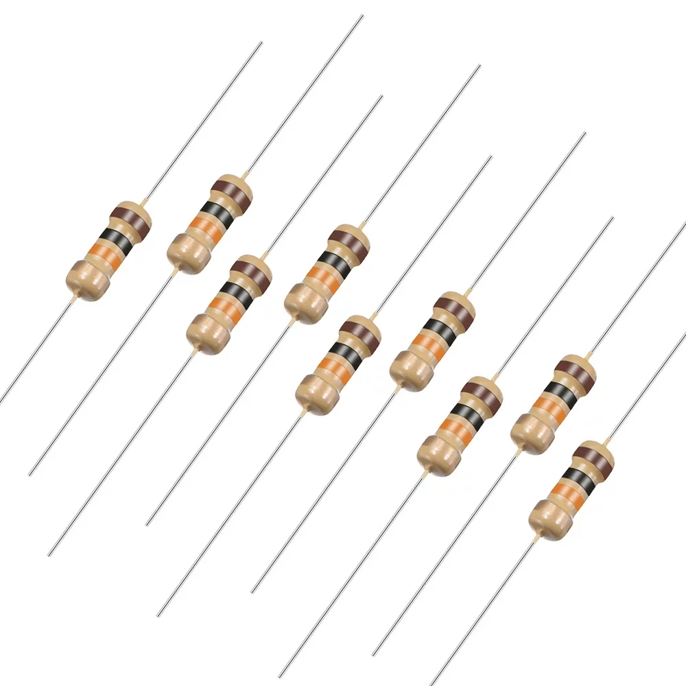
10 Ohm 0.25W Carbon Film Resistor – Pack of 50
Carbon film resistors in various values for building pull-up, pull-down, current-limiting, and base resistor circuits on breadboards.
Choosing the Right Resistor Value
The pull-up or pull-down resistor value involves a trade-off between two competing requirements:
The High-Resistance Side: Power Consumption
When the driver asserts its active state (button pressed, pin driven LOW against a pull-up), current flows continuously through the resistor to the supply rail. Power dissipated: P = V²/R. A lower resistor value wastes more power. For battery-powered devices, you want the resistor as high as possible.
The Low-Resistance Side: Speed and Noise Immunity
Pull-up and pull-down resistors form an RC network with the parasitic capacitance of the wire and input pin (typically 5–50pF for short breadboard connections, up to hundreds of pF for long cables). The RC time constant determines how quickly the line can change state:
τ = R × C
A very large resistor (e.g., 1MΩ) with even 50pF capacitance gives τ = 50µs — too slow for anything above ~3kHz. At higher speeds (I2C at 400kHz, high-speed signals), a smaller pull-up is mandatory. Also, a weaker (higher-resistance) pull-up is more susceptible to picking up noise — the interference current has to be smaller to cause a larger voltage swing on the high-impedance line.
Standard Resistor Values by Application
| Application | Typical Resistor Value | Notes |
|---|---|---|
| Button/switch input (general) | 10kΩ | Good balance of noise immunity and low power |
| I2C bus (100kHz standard mode) | 4.7kΩ | Lower for longer buses; higher for short/low capacitance |
| I2C bus (400kHz fast mode) | 1.8kΩ – 2.2kΩ | Must charge bus capacitance faster |
| MOSFET/BJT gate pull-down | 10kΩ | Keeps gate at GND during startup/idle |
| Open-collector output (single device) | 4.7kΩ – 10kΩ | Higher if multiple devices share the bus |
| Long cable / high-noise environment | 1kΩ – 4.7kΩ | Lower impedance, better noise immunity |
| Ultra-low power (battery, sleep mode) | 100kΩ – 1MΩ | Very low current; check speed requirements |
Internal Pull-Ups in Arduino and Microcontrollers
Most modern microcontrollers — including the ATmega328P used in Arduino Uno — have built-in pull-up resistors on their GPIO pins. These are typically 20–50kΩ and can be enabled in software, eliminating the need for an external resistor for many button and switch applications.
Enabling Internal Pull-Up on Arduino
// Method 1: Using INPUT_PULLUP mode
pinMode(buttonPin, INPUT_PULLUP);
// Now connect button between the pin and GND
// Pin reads HIGH when button is released, LOW when pressed

// Method 2: Write HIGH after setting as INPUT (older syntax)
pinMode(buttonPin, INPUT);
digitalWrite(buttonPin, HIGH);  // Enables internal pull-up
With the internal pull-up enabled, simply connect the button between the pin and GND. No external resistor needed. The logic is active-low (pressed = LOW).
Limitations of Internal Pull-Ups
- Value is 20–50kΩ (varies by temperature and chip) — weaker than most external resistors. May be too weak for noisy environments or long cables.
- Not available on all pins of all microcontrollers — check the datasheet.
- No internal pull-down on ATmega-based Arduinos. Some microcontrollers (STM32, ESP32, RP2040) have configurable internal pull-ups AND pull-downs.
- For I2C and other buses, always use external pull-ups of the specified value — internal pull-ups are too weak.
Pull-Up Resistors on I2C Buses
The I2C protocol uses two lines: SDA (data) and SCL (clock). Both lines are open-drain — devices can only pull them LOW (never drive them HIGH). Pull-up resistors to VCC restore the lines to HIGH when no device is pulling them LOW. Without pull-ups, I2C cannot function at all.
How to Select I2C Pull-Up Values
The I2C specification defines the pull-up value range based on bus capacitance (Cb):
- Minimum pull-up resistance: Rmin = (VCC – 0.4V) / 3mA (the maximum sink current of any I2C device). For 3.3V: Rmin = 2.9V / 3mA ≈ 970Ω. For 5V: Rmin = 4.6V / 3mA ≈ 1.5kΩ.
- Maximum pull-up resistance: Rmax = Rise_time_max / (0.8473 × Cb). For standard mode (100kHz) with Cb = 100pF: Rmax = 1µs / (0.8473 × 100pF) ≈ 11.8kΩ.
For most Arduino and ESP32 projects with short I2C wires (<30cm, a few devices), use 4.7kΩ as a safe universal choice for 5V systems and 2.2kΩ for 3.3V systems at 400kHz. If devices fail to communicate, try reducing the pull-up value.
Common I2C Mistake: Double Pull-Ups
Many I2C modules (OLED displays, BMP280, DS3231 RTC) include pull-up resistors on their PCB. When multiple such modules share an I2C bus, the effective pull-up resistance is the parallel combination of all resistors. Four modules with 4.7kΩ each give 4.7/4 = 1.175kΩ total — too low for 5V systems. Remove or disable pull-ups on all but one module, or replace all with a single appropriately-sized resistor pair.
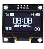
1.3 Inch I2C 128×64 OLED Display Module
An I2C display that requires correct pull-up resistors on the SDA/SCL lines. A real-world example of the I2C pull-up resistor requirement in action.
Pull-Down on MOSFET and Transistor Gates
Floating gate inputs on MOSFETs and transistors are dangerous. A MOSFET gate with no defined voltage can accumulate charge from static electricity or coupling from nearby switching signals and turn ON the MOSFET unexpectedly — potentially destroying the load or creating a short circuit.
Always add a pull-down resistor (10kΩ is standard) between the gate and the source (for MOSFETs) or between the base and emitter (for BJTs). This ensures the transistor is firmly OFF whenever the control signal is not actively driven:
- During Arduino startup (before pinMode is set, outputs are in INPUT mode → floating)
- If the control wire is disconnected
- During a power-on sequence where the microcontroller initialises later than the power stages
The pull-down resistor value of 10kΩ is high enough to not significantly load the gate driver, yet low enough to discharge the gate capacitance within a few microseconds at startup. For very fast switching circuits where the pull-down slows turn-off, use active gate pull-down circuits or lower-value resistors (1kΩ–4.7kΩ).
Open-Collector and Open-Drain Circuits
Many IC outputs use open-collector (BJT) or open-drain (MOSFET) structures. These outputs can only pull the output line LOW — they have no internal connection to VCC. The line can only go HIGH if an external pull-up resistor provides the path to VCC.
Why Open-Drain/Open-Collector?
- Wired-AND logic: Multiple open-drain outputs can share the same line. The line goes LOW if ANY device pulls it LOW. This is exactly how I2C arbitration works.
- Voltage level shifting: An open-drain output from a 3.3V device can drive a 5V pull-up line without level-shifting logic, because the output only pulls to GND (safe) and the pull-up restores the line to the pull-up supply voltage (5V).
- Safety: If two outputs accidentally drive the same line simultaneously, a push-pull driver fights against the other, potentially damaging both. Open-drain outputs can safely share lines because they only sink current, never source it against each other.
Common open-drain/open-collector IC outputs: comparator outputs (LM393, LM311), I2C bus, UART flow control lines, interrupt outputs on many sensors and microcontrollers, relay driver outputs.
Buttons, Debouncing, and Pull Resistors
Mechanical push buttons and toggle switches do not make clean, single contact transitions. The contact surfaces bounce off each other multiple times within 1–50 milliseconds, generating a burst of rapid transitions. A microcontroller sampling the button input at 1MHz would see dozens of spurious press/release events before the contact settles.
RC Debounce with Pull-Up
Adding a capacitor from the input pin to GND, combined with the pull-up resistor, creates an RC filter that smooths out the bounces:
- Pull-up resistor: 10kΩ
- Debounce capacitor: 100nF (gives τ = 10kΩ × 100nF = 1ms)
- Button: between input pin and GND
When the button closes, the capacitor charges slowly through the resistor and the button contact resistance, smoothing out any bounce. The typical bounce lasts <5ms; with a 1ms time constant, the filter smooths the input cleanly. You still need software debouncing for reliable behaviour, but this hardware filter prevents the worst oscillations from reaching the digital input.
Software Debouncing with Pull-Up
Using Arduino with INPUT_PULLUP and software debouncing:
const int buttonPin = 2;
const unsigned long debounceDelay = 50; // 50ms debounce time

int lastButtonState = HIGH;  // Pull-up: default HIGH
int buttonState = HIGH;
unsigned long lastDebounceTime = 0;

void setup() {
  pinMode(buttonPin, INPUT_PULLUP);
  Serial.begin(9600);
}

void loop() {
  int reading = digitalRead(buttonPin);

  if (reading != lastButtonState) {
    lastDebounceTime = millis(); // Reset debounce timer
  }

  if ((millis() - lastDebounceTime) > debounceDelay) {
    if (reading != buttonState) {
      buttonState = reading;
      if (buttonState == LOW) {
        Serial.println("Button pressed!");
      }
    }
  }
  lastButtonState = reading;
}

0 Ohm 0.25W Carbon Film Resistor – Pack of 100
Zero-ohm jumpers for PCB layout, useful when building prototype circuits requiring optional pull-up or pull-down resistor positions as solder bridges.
Common Mistakes with Pull-Up and Pull-Down Resistors
- Using a pull-up on an output pin: If you configure a GPIO as an output and also connect an external pull-up, the pull-up fights against the output when it drives LOW, wasting current (and potentially damaging a weak output). Only use pull-ups/pull-downs on input lines or open-drain output lines.
- Connecting pull-up to the wrong voltage: If a 5V pull-up is connected to a 3.3V microcontroller GPIO, the input voltage exceeds the 3.3V absolute maximum and will damage the chip. Match pull-up voltage to the logic level of the receiving device.
- No pull resistor on a MOSFET gate: Results in random turn-on during startup, potentially destroying the load. Always add a 10kΩ pull-down on every MOSFET gate.
- Value too high for I2C: I2C at 400kHz requires pull-ups of 1.8–2.2kΩ for 3.3V systems. Using 10kΩ creates too-slow rise times; signals look rounded and devices fail to communicate or suffer data corruption.
- Stacking multiple module pull-ups in parallel: Each I2C module board adds its own pull-ups. Three modules × 4.7kΩ = 1.57kΩ effective pull-up. This over-drives the bus and violates I2C spec. Check module schematics and remove extra pull-up resistors (or bridge the pull-up pads with solder to disable them).
Frequently Asked Questions
What is the difference between a pull-up and a pull-down resistor?
A pull-up resistor connects the signal line to VCC, defining the default (inactive) state as HIGH. A pull-down resistor connects the signal line to GND, defining the default state as LOW. The choice depends on how your signal source drives the line and which logic convention (active-low vs active-high) you prefer for your circuit.
Do I always need an external pull-up or pull-down resistor?
Not always. Microcontrollers like Arduino have built-in pull-up resistors (enable with INPUT_PULLUP) that eliminate the need for external components on button inputs. However, for I2C buses, open-drain outputs, MOSFET gate pull-downs, and any application requiring a specific impedance, always use external resistors of the correct value.
Can I use any resistor value for a pull-up or pull-down?
Within limits, yes. Too high a value (above ~100kΩ) makes the line susceptible to noise and may be too slow for the required signal speed. Too low a value (below ~1kΩ for most applications) wastes too much current when the driver holds the line in its active state. The exact acceptable range depends on the application — see the value table in this article.
Why does my I2C device not work even though I added pull-up resistors?
Common causes: (1) Pull-up resistors are too large for your bus speed and capacitance — try reducing the value. (2) Pull-up voltage is wrong — 5V pull-ups on a 3.3V I2C device can damage it. (3) Multiple modules each have their own pull-ups creating an excessively low total resistance. (4) The I2C address is incorrect — pull-ups are correct but the address in your code does not match the device. Use an I2C scanner sketch to verify the device address.
What happens if I use a pull-up resistor on an I2C line that already has internal pull-ups in the microcontroller?
The effective pull-up resistance is the parallel combination of the external and internal resistors. Since Arduino’s internal pull-ups are 20–50kΩ, adding a 4.7kΩ external pull-up gives approximately 4.3kΩ effective — essentially just the external resistor dominates. This is fine; the internal pull-up just contributes a small extra pull-up current that is negligible.
Can pull-up resistors be used to interface 3.3V and 5V systems safely?
For open-drain/open-collector signals, yes. Connect the pull-up to the 3.3V side (not 5V) when the signal is being received by a 3.3V device. The 5V device’s open-drain output can pull the line to GND safely, and the 3.3V pull-up raises it to 3.3V — within the input range of the 5V device (typically accepts 2V+ as HIGH). This is the standard, bidirectional I2C level-shifting technique used with a BSS138 MOSFET or similar.
Zbotic stocks carbon film, metal film resistors, capacitors, and more — delivered fast across India. Shop Electronics Components at Zbotic


Add comment