
The op-amp 741 and LM358 are two of the most widely used operational amplifiers in hobbyist electronics and engineering education in India. Whether you are building a comparator circuit, a voltage amplifier, a Schmitt trigger, or a simple temperature alarm, understanding the differences between these two ICs — and knowing which comparator and amplifier configurations to use — is essential. This guide covers everything from internal architecture to practical breadboard circuits for Arduino-based projects.
Table of Contents
- Operational Amplifier Basics
- µA741 Op-Amp: The Classic Workhorse
- LM358 Dual Op-Amp: Low Power, Single Supply
- 741 vs LM358: Head-to-Head Comparison
- Comparator Circuit: Theory and Design
- Inverting Amplifier Circuit
- Non-Inverting Amplifier Circuit
- Practical Projects: Temperature Alarm and Light Sensor
- Frequently Asked Questions
Operational Amplifier Basics
An operational amplifier (op-amp) is a high-gain DC-coupled differential amplifier with a very high input impedance and a very low output impedance. Its key characteristic: it amplifies the difference between its two input terminals (V+ and V−) by an enormous open-loop gain (typically 100,000 to 1,000,000).
The fundamental op-amp equation (open-loop):
Vout = A_ol × (V+ − V−)
Where A_ol is the open-loop voltage gain. With such high gain, even a 1µV difference between inputs drives the output to the positive or negative supply rail. This is what makes op-amps useful as comparators.
When negative feedback is added (a resistor from output back to the inverting input V−), the op-amp gain is precisely controlled by the feedback network, enabling stable amplifier designs. This is the basis of all closed-loop amplifier configurations.
Key op-amp parameters:
- Input Offset Voltage (Vos): Small DC voltage mismatch between inputs. Causes output error even with zero differential input.
- Input Bias Current (Ib): Small current drawn by each input. Causes voltage drop across source impedances.
- Slew Rate (SR): Maximum rate of output voltage change (V/µs). Limits high-frequency large-signal performance.
- Gain-Bandwidth Product (GBW): The frequency at which the open-loop gain drops to 1 (0 dB). Determines useful amplifier bandwidth.
- CMRR (Common Mode Rejection Ratio): Ability to reject signals common to both inputs. Higher is better.
- Supply Voltage Range: The range of power supply voltages the op-amp can operate from.
µA741 Op-Amp: The Classic Workhorse
The µA741 (simply called the 741) was introduced by Fairchild Semiconductor in 1968 and became the defining operational amplifier IC of the 20th century. It is an internally compensated, 8-pin DIP package, single op-amp that requires a split (dual) power supply for most applications.
µA741 Key Specifications
| Parameter | Value |
|---|---|
| Supply Voltage | ±5V to ±18V (dual supply) |
| Input Offset Voltage | 1–6 mV typical |
| Input Bias Current | 80 nA typical |
| Open-Loop Gain | 200 V/mV (106 dB) |
| Slew Rate | 0.5 V/µs |
| Gain-Bandwidth Product | 1 MHz |
| Output Short-Circuit Protected | Yes |
| Single Supply Operation | Not recommended (output cannot swing near GND) |
741 Pinout (DIP-8)
Pin 1 = Offset Null, Pin 2 = Inverting Input (V−), Pin 3 = Non-Inverting Input (V+), Pin 4 = V−(supply), Pin 5 = Offset Null, Pin 6 = Output, Pin 7 = V+(supply), Pin 8 = NC (No Connect).
The 741 requires a split supply (e.g., +12V and −12V) for its output to swing both positive and negative. Operating it from a single 5V supply (as used by Arduino) results in the output not being able to swing below about 1–2V, limiting its usefulness in single-supply circuits.
When to Use the 741
- Educational lab experiments with split ±12V or ±15V supplies
- Audio frequency amplifiers (bandwidth up to 10kHz with closed-loop gain)
- Integrator and differentiator circuits
- When you already have a split supply in your design
LM358 Dual Op-Amp: Low Power, Single Supply
The LM358 was introduced by National Semiconductor (now Texas Instruments) in 1972 as a dual op-amp specifically designed for single-supply operation. It contains two independent op-amps in a single 8-pin DIP package, with an output stage that can swing down to GND — making it ideal for 5V or 3.3V microcontroller-based systems.
LM358 Key Specifications
| Parameter | Value |
|---|---|
| Supply Voltage | 3V to 32V single, or ±1.5V to ±16V dual |
| Input Offset Voltage | 2–7 mV typical |
| Input Bias Current | 45 nA typical |
| Open-Loop Gain | 100 V/mV (100 dB) |
| Slew Rate | 0.3–0.6 V/µs |
| Gain-Bandwidth Product | 1 MHz |
| Output Swing (single supply) | 0V to Vcc − 1.5V |
| Quiescent Current (per amplifier) | 500 µA typical |
| Number of Op-Amps | 2 (dual) |
LM358 Pinout (DIP-8)
Op-Amp A: Pin 1 = Output, Pin 2 = Inverting Input, Pin 3 = Non-Inverting Input. Op-Amp B: Pin 5 = Non-Inverting Input, Pin 6 = Inverting Input, Pin 7 = Output. Pin 4 = GND, Pin 8 = VCC.
The LM358 is perfect for 5V Arduino circuits because both inputs can accept 0V to VCC signals and the output can swing from 0V (or very close) up to VCC − 1.5V. You get two independent op-amps in one package, saving board space and cost.
741 vs LM358: Head-to-Head Comparison
| Feature | µA741 | LM358 |
|---|---|---|
| Amplifiers per IC | 1 | 2 |
| Single Supply | Not recommended | Yes (3V–32V) |
| Output Swing (5V) | ~1.5V to ~3.5V | ~0V to ~3.5V |
| Input Offset | 1–6 mV | 2–7 mV |
| Slew Rate | 0.5 V/µs | 0.3 V/µs |
| GBW | 1 MHz | 1 MHz |
| Best For | Lab experiments, split-supply designs | Arduino/microcontroller circuits, single-supply |
| Cost | Similar / slightly higher | Low, very widely available |
Verdict for Indian makers: For virtually all Arduino, ESP32, and single-supply hobbyist projects, the LM358 is the better choice. The 741 is better suited for educational lab work with a split ±12V supply. Both are limited to 1 MHz bandwidth — for audio amplifier projects above 10kHz gain-bandwidth, consider the TL071, NE5532, or TL082 which offer 3–10 MHz GBW and higher slew rates.
Comparator Circuit: Theory and Design
A comparator circuit uses the op-amp’s high open-loop gain to compare two voltages. When V+ > V−, the output swings to the positive supply rail (HIGH). When V+ < V−, the output swings to the negative supply rail (LOW).
Basic Op-Amp Comparator
LM358 Comparator Circuit:

        +5V
         |
       [R1=10k]
         |
  V+ ---[Non-Inv Input]
         |               Output → Arduino GPIO or LED
  V− ---[Inv Input] ---- [LM358 Output]
         |
       [R2=10k]
         |
        GND

V+ = Sensor signal (e.g., LM35 temperature, LDR voltage divider)
V− = Reference voltage (voltage divider from VCC)
When the sensor voltage rises above the reference voltage, the output goes HIGH. This is the basis of a temperature alarm, light sensor threshold detector, or battery over-voltage detector.
Schmitt Trigger Comparator (with Hysteresis)
A basic comparator will oscillate rapidly (chatter) when the input signal is close to the reference threshold and has noise. Adding positive feedback via a resistor from output to the non-inverting input (V+) creates hysteresis — a defined upper and lower threshold — preventing chatter. This is called a Schmitt trigger.
The hysteresis band width: ΔV = Vout_swing × (R_pos_feedback / R_divider)
For most Arduino-compatible threshold detectors, 50–200mV of hysteresis eliminates relay chatter and LED flickering near the threshold.

LM35 Temperature Sensor
Linear analog temperature sensor — outputs 10mV per °C. Perfect for LM358 comparator-based temperature alarm circuits. 0°C to 100°C range, 5V operation.
Inverting Amplifier Circuit
The inverting amplifier configuration uses negative feedback to set a precise, stable voltage gain. The output is inverted (180° phase shift) relative to the input.
Inverting Amplifier Formula
         Rf
   ┌────[Rf]────┐
   │             │
Vin─[Rin]──(V−)─[LM358]──Vout
              │
           (V+)─ GND (or Vref for single supply)

Gain = −Rf / Rin  (negative = inverted)
Example: For a gain of −10, use Rf = 100kΩ and Rin = 10kΩ. Input 0.1V gives output −1V (or +1V below the virtual ground reference in a single-supply design).
Inverting Amplifier Design Rules
- Use a virtual ground at Vcc/2 for single-supply inverting amplifiers (bias V+ to 2.5V via equal voltage divider)
- Keep Rf below 1MΩ to minimise noise pickup and input bias current effects
- Add a capacitor in series with Rin to create an AC-coupled amplifier (blocks DC, passes AC signals only)
- Match Rin with a feedback resistor from V+ to GND (equal to Rf || Rin) to cancel input bias current offset
Non-Inverting Amplifier Circuit
The non-inverting amplifier has a gain greater than +1 and the output is in phase with the input. The signal connects to V+ and the feedback divider connects from output to V−.
Non-Inverting Amplifier Formula
Vin ─── (V+) ─[LM358]─── Vout
                │
              [Rf]
                │
              (V−)
                │
              [R1]
                │
               GND

Gain = 1 + (Rf / R1)
Example: For a gain of +11, use Rf = 100kΩ and R1 = 10kΩ. Input 0.1V gives output +1.1V.
A unity-gain buffer (voltage follower) is a special case of the non-inverting amplifier where Rf = 0 and R1 = ∞ (output directly connects to V−). This gives gain = 1 with extremely high input impedance and low output impedance — used to buffer signals from high-impedance sources like sensors.

10CM Female To Female Breadboard Jumper Wires — 40Pcs
Essential for breadboarding op-amp circuits. Use F-F wires to connect Arduino analog outputs to op-amp inputs and route op-amp output to sensor modules.
Practical Projects: Temperature Alarm and Light Sensor
Project 1: LM358 Temperature Threshold Alarm using LM35
This comparator circuit triggers an LED and buzzer when temperature exceeds 40°C.
Components: LM358, LM35 temperature sensor, 10kΩ potentiometer (threshold adjust), LED, 220Ω resistor, BC547 NPN transistor, 5V buzzer, 5V supply.
Circuit:
- LM35 Vout (10mV/°C) → LM358 V+ (non-inverting input)
- Potentiometer wiper → LM358 V− (inverting input). Set pot to give 0.40V at wiper for 40°C threshold.
- LM358 output → 10kΩ → BC547 base → LED + buzzer to VCC → BC547 collector. BC547 emitter → GND.
- When temp > 40°C, LM35 output > 0.40V → LM358 output HIGH → BC547 turns ON → alarm activates.
Project 2: LM358 Light-Dependent Resistor (LDR) Night Light
Automatically turns on an LED when ambient light falls below a threshold.
Components: LM358, LDR, 10kΩ fixed resistor, 10kΩ potentiometer, LED, 220Ω resistor.
Circuit:
- LDR and 10kΩ resistor form a voltage divider: LDR to VCC, 10kΩ to GND, midpoint to LM358 V+.
- In bright light: LDR resistance is low → V+ is low. In dark: LDR resistance is high → V+ is high.
- Potentiometer sets reference voltage at LM358 V−.
- LM358 output HIGH in dark (V+ > V−) → LED turns ON.
Reading the LM358 Output with Arduino
The LM358 output connected to an Arduino analog pin can give a precise voltage reading. Use analogRead(A0) and map the 0–1023 ADC value to 0–5000 mV for threshold calculation in software. This gives the best of both worlds: hardware-fast analog comparator response plus software flexibility.
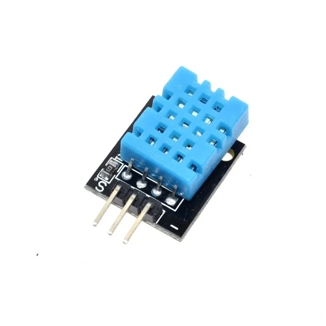
DHT11 Digital Temperature and Humidity Sensor Module
Digital sensor for temperature and humidity — complement your analog LM358 comparator circuit with digital sensing for cross-verification and data logging on Arduino.
Other Essential Op-Amp Configurations
Summing Amplifier (Mixer)
Multiple input resistors connect to the inverting input, each carrying a different signal. The output is the weighted sum of all inputs (inverted). Used in audio mixing and DAC circuits.
Integrator Circuit
Replace Rf with a capacitor in the inverting amplifier configuration. Output is the integral of the input over time. Used in waveform generators, ADCs, and control systems.
Differentiator Circuit
Replace Rin with a capacitor. Output is proportional to the rate of change of the input. Used in edge detection and signal processing.
Instrumentation Amplifier
Three op-amps configured for extremely high CMRR and precise differential gain — used in strain gauge, thermocouple, and biomedical sensor circuits. The INA128 and INA129 are dedicated single-chip instrumentation amplifiers based on this topology.
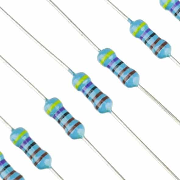
Metal Film Resistor MFR — Pack of 100
1% tolerance metal film resistors for precision op-amp gain networks and voltage dividers. Essential for accurate inverting and non-inverting amplifier designs.
Decoupling Capacitors for Op-Amps
Every op-amp power pin must have a 100nF ceramic decoupling capacitor placed as close as possible to the VCC and GND pins. Without this, the op-amp can oscillate at high frequencies due to supply noise, producing unexpected behaviour. For audio applications, add a 10µF electrolytic in parallel with the 100nF ceramic for low-frequency supply decoupling.
Frequently Asked Questions
Can I use the LM358 as a comparator with Arduino 5V supply?
Yes. The LM358 is specifically designed for single-supply operation down to 3V. On a 5V Arduino supply, the LM358 output can swing from approximately 0V to 3.5V. Connect the output to an Arduino digital GPIO configured as INPUT — the Arduino will read anything above 2.5V as HIGH and below 0.8V as LOW. This works well for simple threshold detection circuits.
What is the difference between an op-amp and a comparator IC?
A dedicated comparator IC (like the LM393 or LM311) is optimised for open-loop operation with fast switching, rail-to-rail output swing, and often an open-collector or open-drain output stage for direct logic interfacing. An op-amp used as a comparator works but is slower (limited slew rate), may oscillate near the threshold due to internal compensation, and has limited output swing. For critical applications, always use a dedicated comparator. For casual threshold detection in hobbyist circuits, the LM358 works fine as a comparator.
Why does my op-amp output not reach 5V on a 5V supply?
The LM358 and µA741 are not rail-to-rail output op-amps. Their output typically swings to within 1–2V of each supply rail. On a 5V supply, the maximum output is approximately 3.5V. For rail-to-rail output that reaches all the way to 5V, use rail-to-rail op-amps like the MCP6001, LMV358, or OPA2134.
What is virtual ground and why do I need it for the 741 on single supply?
The 741 was designed for split-supply (e.g., ±12V) operation, where 0V is the mid-rail. On single supply, the mid-rail is VCC/2 (2.5V for 5V supply). To use a 741 on single supply, bias the V+ input to VCC/2 using two equal resistors (10kΩ each) forming a voltage divider — this becomes the virtual ground reference. All signal references are then measured relative to VCC/2. The LM358 avoids this complication by natively operating on single supply.
How do I calculate the closed-loop bandwidth of my op-amp amplifier?
For both the 741 and LM358 (1 MHz GBW): Bandwidth = GBW / Gain. For a gain of 10, bandwidth = 1 MHz / 10 = 100 kHz. For a gain of 100, bandwidth = 1 MHz / 100 = 10 kHz. This means high-gain amplifiers have limited bandwidth — a fundamental trade-off in BJT op-amps. For wider bandwidth at high gain, choose an op-amp with higher GBW (e.g., TL071 at 3 MHz, NE5534 at 10 MHz).
Conclusion: Master Op-Amps and Unlock Analog Electronics
The LM358 is the practical choice for every Indian maker working with Arduino and single-supply circuits — two op-amps in one package, single-supply compatible, widely available, and low cost. The 741 remains valuable in educational settings with split power supplies. Master the comparator, inverting amplifier, and non-inverting amplifier configurations using breadboard prototypes, and you will have the foundation to tackle signal conditioning, sensor interfacing, audio amplification, and automatic control circuits. Add an LM35 temperature sensor and metal film resistors to your kit, and start experimenting today!


Add comment