
HC-SR501 PIR Wireless Alert: NRF24L01 Security System Project
If you are looking to build a PIR NRF24L01 wireless security Arduino system at home without spending thousands of rupees on commercial alarm systems, this project is exactly what you need. Using the affordable HC-SR501 passive infrared sensor and the NRF24L01 2.4 GHz radio module, you can create a reliable multi-zone wireless intruder alert system that covers your entire home — all for under ₹500 in components. Indian hobbyists and makers have been building such systems for years, and in 2026, the parts are cheaper and better documented than ever.
How the PIR + NRF24L01 System Works
The HC-SR501 PIR sensor detects infrared radiation emitted by warm bodies — humans, animals, or even a hot chai cup moving across the room. When motion is detected, the sensor outputs a HIGH signal on its output pin. In this project, an Arduino Nano (or Uno) reads this signal and immediately transmits a radio packet using the NRF24L01 module operating at 2.4 GHz.
At the receiving end — perhaps your bedroom or a central hub — another Arduino with an NRF24L01 listens for incoming packets. When it receives an alert, it can trigger a buzzer, light an LED, send an SMS via a GSM module, or activate a relay to switch on lights. The beauty of this architecture is that you can place multiple sensor nodes throughout your house — entrance, garage, terrace — and all of them report to a single base station.
The NRF24L01 operates at 2.4 GHz with a range of up to 100 metres in open space (about 20–30 metres through walls, which is sufficient for most Indian homes). It uses SPI communication and the popular RF24 library, making coding straightforward even for beginners.
Components You Need
Here is everything required for a single-zone system. Multiply the sensor-side components for multi-zone setups.
- 2× Arduino Nano (one transmitter, one receiver)
- 2× NRF24L01 2.4 GHz wireless module
- 1× HC-SR501 PIR motion sensor
- 1× Active buzzer (5V)
- 1× 0.96-inch OLED display (optional, for status readout at base)
- 100µF capacitor across NRF24L01 VCC-GND (critical — reduces noise)
- Jumper wires, breadboard
- 5V USB power bank or 3× AA battery pack
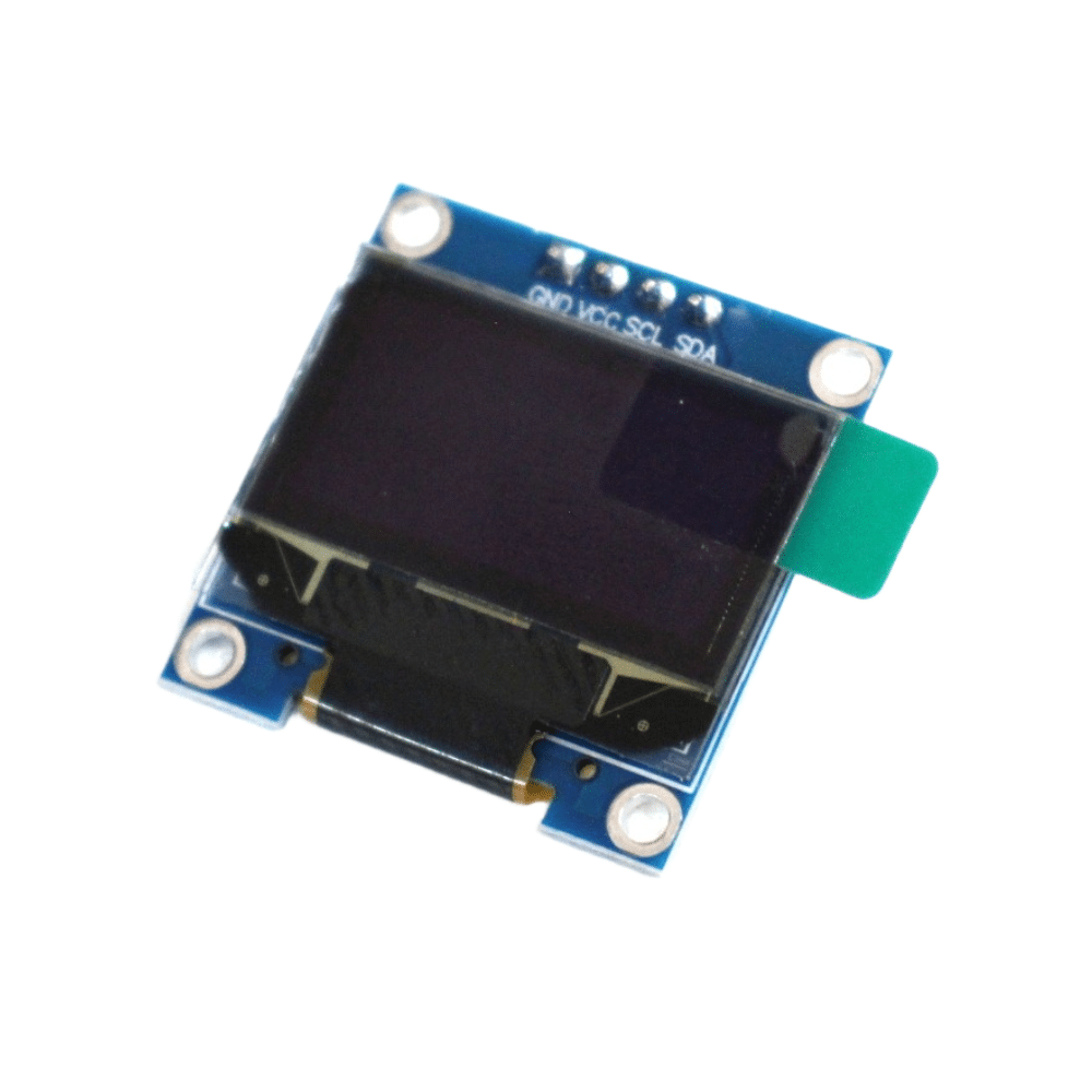
0.96 Inch I2C IIC OLED LCD Module 4pin White SSD1306 Chip
Display real-time zone alerts and timestamps at your base station with this crisp white OLED. Works with SSD1306 library and Arduino Nano over just 2 wires.
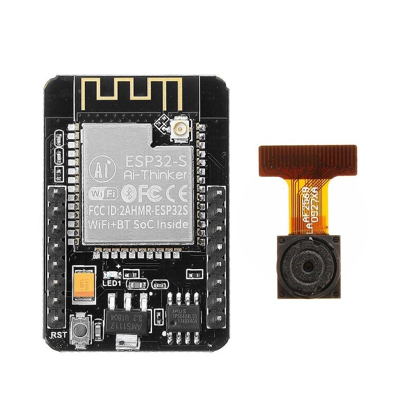
Ai Thinker ESP32 CAM Development Board WiFi+Bluetooth
Upgrade your base station by replacing the Arduino receiver with an ESP32-CAM — capture a photo on motion detection and send it via WhatsApp or Telegram instantly.
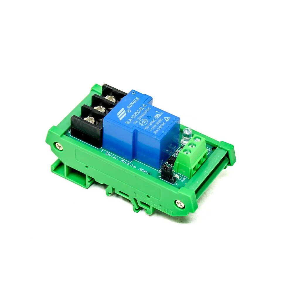
1 Channel 12V 30A Relay Module with Optocoupler and Guide Rail
Trigger a 12V siren, floodlight, or door lock when the base station receives a motion alert. Optocoupler isolation protects your Arduino from voltage spikes.
Circuit and Wiring Guide
The NRF24L01 requires 3.3V power — not 5V. Powering it at 5V will permanently damage the module. Always use the Arduino’s 3.3V pin and add a 100µF capacitor between VCC and GND as close to the module as possible. This single capacitor eliminates 80% of NRF24L01 connection problems that beginners face.
NRF24L01 to Arduino Nano Pinout
| NRF24L01 Pin | Arduino Nano Pin |
|---|---|
| VCC | 3.3V |
| GND | GND |
| CE | D9 |
| CSN | D10 |
| SCK | D13 |
| MOSI | D11 |
| MISO | D12 |
Connect the HC-SR501 OUT pin to Arduino D2 (interrupt-capable), VCC to 5V, and GND to GND. Adjust the PIR’s two potentiometers — sensitivity (right, clockwise for higher sensitivity) and time delay (left, counter-clockwise for minimum 3-second delay). Set the jumper to single-trigger mode (H position) for security applications.
Arduino Transmitter Code (Sensor Node)
Install the RF24 library by TMRh20 from the Arduino Library Manager before uploading this sketch.
#include <SPI.h>
#include <RF24.h>

RF24 radio(9, 10); // CE, CSN
const byte address[6] = "00001";
const int PIR_PIN = 2;

void setup() {
  pinMode(PIR_PIN, INPUT);
  radio.begin();
  radio.openWritingPipe(address);
  radio.setPALevel(RF24_PA_LOW); // Use HIGH for longer range
  radio.stopListening();
  delay(2000); // PIR warm-up
}

void loop() {
  if (digitalRead(PIR_PIN) == HIGH) {
    const char msg[] = "MOTION ZONE1";
    radio.write(&msg, sizeof(msg));
    delay(500); // Debounce
  }
}
For multi-zone systems, change "ZONE1" to "ZONE2", "ZONE3" etc. on each node, and use different pipe addresses to avoid packet collisions.
Arduino Receiver Code (Base Station)
#include <SPI.h>
#include <RF24.h>
#include <Wire.h>
#include <Adafruit_SSD1306.h>

RF24 radio(9, 10);
const byte address[6] = "00001";
Adafruit_SSD1306 display(128, 64, &Wire, -1);
const int BUZZER_PIN = 6;

void setup() {
  Serial.begin(9600);
  pinMode(BUZZER_PIN, OUTPUT);
  radio.begin();
  radio.openReadingPipe(0, address);
  radio.setPALevel(RF24_PA_LOW);
  radio.startListening();
  display.begin(SSD1306_SWITCHCAPVCC, 0x3C);
  display.clearDisplay();
  display.setTextColor(WHITE);
  display.setCursor(0, 0);
  display.println("Security Active");
  display.display();
}

void loop() {
  if (radio.available()) {
    char msg[32] = "";
    radio.read(&msg, sizeof(msg));
    Serial.println(msg);
    // Sound buzzer
    for (int i = 0; i < 3; i++) {
      digitalWrite(BUZZER_PIN, HIGH);
      delay(200);
      digitalWrite(BUZZER_PIN, LOW);
      delay(100);
    }
    // Update OLED
    display.clearDisplay();
    display.setCursor(0, 0);
    display.println("!! ALERT !!");
    display.setCursor(0, 20);
    display.println(msg);
    display.display();
    delay(5000);
    display.clearDisplay();
    display.setCursor(0, 0);
    display.println("Security Active");
    display.display();
  }
}
Expanding to Multi-Zone Coverage
The NRF24L01 supports up to 6 pipes simultaneously on a single receiver. This means you can monitor 6 zones with one base station. Assign each transmitter a unique pipe address and open all pipes on the receiver:
const byte addresses[][6] = {"Zone1","Zone2","Zone3"};
// Receiver:
radio.openReadingPipe(1, addresses[0]);
radio.openReadingPipe(2, addresses[1]);
radio.openReadingPipe(3, addresses[2]);
For larger homes in India with thick RCC walls, use the NRF24L01+PA+LNA variant with an external antenna, which extends range to 500+ metres in open space. Place the base station centrally and orient antennas vertically for best penetration through walls. Alternatively, you can daisy-chain nodes as repeaters using the RF24Network library.
Power Supply and Battery Tips for Indian Conditions
Power cuts are common in India, so designing your sensor nodes to run on batteries is essential. A single 18650 Li-ion cell (3.7V, 2000mAh) with a TP4056 charging module and a 5V boost converter can power a node for 3–6 months using sleep mode. Add this to the transmitter loop:
#include <avr/sleep.h>
#include <avr/interrupt.h>

ISR(INT0_vect) { /* PIR interrupt wakes MCU */ }

void deepSleep() {
  set_sleep_mode(SLEEP_MODE_PWR_DOWN);
  sleep_enable();
  attachInterrupt(0, [](){}, RISING); // D2 = INT0
  sleep_mode();
  sleep_disable();
}
In sleep mode, the Arduino Nano draws only ~0.1µA (with power LED removed). The NRF24L01 in power-down mode draws 900nA. This combination extends battery life dramatically compared to polling loops. For solar-powered outdoor nodes, pair a 5V/1W solar panel with a 1000mAh LiPo and a solar charge controller module.

0.96 Inch SPI OLED LCD Module + CSpin 7pin White SSD1306 Chip
High-contrast SPI OLED for fast base station display updates. SPI interface frees up I2C for other sensors like temperature or humidity monitoring.
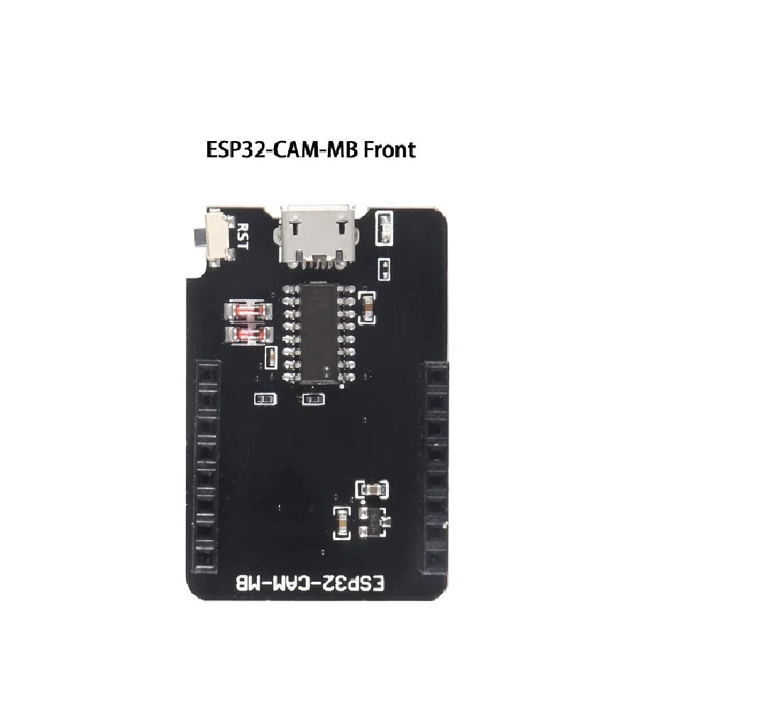
ESP32-CAM-MB MICRO USB Download Module for ESP32 CAM
Program your ESP32-CAM base station without a separate USB-TTL adapter. The MB board adds a convenient Micro-USB port and reset button for hassle-free flashing.
Frequently Asked Questions
Does the NRF24L01 need a license to operate in India?
No. The 2.4 GHz ISM band used by the NRF24L01 is license-exempt in India under WPC (Wireless Planning and Coordination) regulations, just like Wi-Fi and Bluetooth. You can freely use it for hobby and personal projects without any permits.
My NRF24L01 is not communicating — what should I check first?
The most common cause is insufficient power. Add a 100µF electrolytic capacitor across VCC and GND on the NRF24L01 module. Also verify you are powering it from 3.3V (not 5V) and that both modules use the same channel and address bytes. Use radio.printDetails() on Serial Monitor to check configuration.
Can I use this system with an ESP8266 instead of Arduino?
Yes. The ESP8266 supports SPI and works with the RF24 library. The advantage is that the ESP8266’s Wi-Fi lets you send Telegram or WhatsApp alerts. Note that the ESP8266 GPIO runs at 3.3V logic, which is compatible with the NRF24L01. Use a logic level shifter only if connecting to Arduino Uno’s 5V pins.
How far can the NRF24L01 transmit through concrete walls?
Standard NRF24L01: 20–30 metres through 2–3 walls. NRF24L01+PA+LNA with external antenna: 50–80 metres through walls. For Indian RCC construction (thick walls + steel reinforcement), the PA+LNA variant is highly recommended. Reduce data rate to 250 kbps for better wall penetration.
Is HC-SR501 affected by Indian summer heat above 40°C?
The HC-SR501 is rated for –20°C to +80°C operation, so Indian summer temperatures pose no issue. However, when ambient temperature approaches body temperature (36–37°C), detection sensitivity reduces. Adjust the sensitivity potentiometer clockwise to compensate. For outdoor installations, shield the sensor from direct sunlight to avoid false triggers from rapid temperature changes.
Build Your Wireless Security System Today
Get all the components — NRF24L01 modules, OLEDs, relay modules, and ESP32 boards — delivered fast across India from Zbotic. Free shipping on orders above ₹999.


Add comment