
Multimeter Guide: Voltage, Current and Resistance Measurement for Beginners
A multimeter guide covering voltage, current and resistance measurement is every electronics hobbyist’s starting point. Whether you are debugging an Arduino circuit at midnight or checking whether your 12V SMPS is delivering the right output, a multimeter is the single most essential tool on your workbench. In this comprehensive guide, we will walk through everything — from understanding the dial positions to safely measuring live circuits — so you can get the most out of your multimeter from day one.
What Is a Multimeter and How Does It Work?
A multimeter — also called a VOM (Volt-Ohm-Milliammeter) — is an electronic measuring instrument that combines several measurement functions into one handheld device. At its core, it measures three fundamental electrical quantities:
- Voltage (V): The electrical potential difference between two points
- Current (A): The flow of electric charge through a circuit
- Resistance (Ω): The opposition to current flow in a material
Modern digital multimeters (DMMs) use an analog-to-digital converter (ADC) internally. When you probe a circuit, the instrument converts the raw electrical signal into a digital reading shown on the LCD display. Auto-ranging multimeters automatically select the best measurement range, while manual-ranging meters require you to select the range yourself — the latter are faster for experienced users and often cheaper.
In India, most hobbyists start with an affordable manual-range meter (like the classic DT-830 series) and graduate to auto-ranging units as their projects become more complex. For Arduino and Raspberry Pi tinkerers, even a basic ₹300 multimeter can diagnose 90% of common circuit faults.
Parts of a Multimeter You Must Know
Before you start probing anything, familiarise yourself with these key parts:
- Display: Usually a 3.5-digit or 4-digit LCD showing the measured value and unit
- Rotary Dial (Range Selector): Selects measurement type (V, A, Ω) and range
- COM Port (Black): Common ground — always plug the black probe here
- VΩmA Port (Red): For voltage, resistance, and small current measurements
- 10A / 20A Port (Red): For measuring large currents only — do NOT use for voltage
- Probes: Red (positive) and black (negative/ground) test leads
- Hold Button: Freezes the reading on screen for convenience
A critical safety note: always insert the red probe into the correct port before measuring. Using the current port (10A) for a voltage measurement will blow the internal fuse immediately — sometimes without any warning.
How to Measure Voltage (DC and AC)
Voltage measurement is by far the most common multimeter task. Here is the step-by-step process:
DC Voltage (Battery, Arduino, Power Supply)
- Insert the red probe into the VΩmA port and black into COM
- Turn the dial to the DCV (DC Voltage) section
- Select a range higher than the voltage you expect — for a 9V battery, choose 20V
- Touch the red probe to the positive terminal and black to the negative
- Read the display — a positive reading confirms correct polarity
AC Voltage (Mains Power)
- Set dial to ACV (AC Voltage) — in India, mains is 230V AC, so select the 750V range
- AC has no polarity, so probe placement does not matter directionally
- Never touch bare metal on probes when measuring mains voltage
Pro Tip: When debugging a 12V SMPS or Arduino power rail, always measure with the circuit under load (i.e., connected to your components). An unloaded reading will always be slightly higher than the actual working voltage.
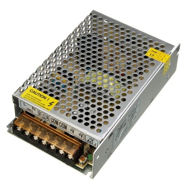
12V 10A SMPS – 120W DC Metal Power Supply
A reliable 120W DC power supply for bench testing. Verify its output voltage precisely with your multimeter before connecting sensitive components.
How to Measure Current (Amperage)
Measuring current is the trickiest part of multimeter use because the meter must be placed in series with the circuit — not in parallel like voltage measurement. This means you must break the circuit and insert the multimeter as part of it.
Steps to Measure DC Current
- Estimate the current first (use Ohm’s Law: I = V/R if needed)
- If current is below 200mA: use the VΩmA port with red probe
- If current may exceed 200mA: use the 10A port to protect the meter
- Set the dial to DC Amperes (A or mA as appropriate)
- Break the circuit — disconnect one wire
- Connect the multimeter in series: current flows INTO red, OUT from black (COM)
- Power the circuit and read the display
- Reconnect the wire directly after measurement
Warning: Never leave a multimeter in current mode when probing voltage points. The low internal resistance of current mode will create a short circuit and blow the fuse — or worse, damage the meter permanently.
For Arduino projects, you typically measure current draw of modules like OLED displays, sensor boards, or motor drivers. Knowing the exact draw helps you choose the right power supply and avoid overloading your 3.3V or 5V rails.
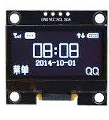
1.3 Inch I2C 128×64 OLED Display Module
A popular display module for Arduino projects. Use your multimeter to verify it draws under 20mA before connecting directly to an Arduino pin.
How to Measure Resistance with a Multimeter
Resistance measurement is straightforward but requires one golden rule: always measure resistance out-of-circuit (with power off and the component removed or isolated). Measuring resistance in a powered circuit gives meaningless readings and can damage the meter.
Steps to Measure Resistance
- Power off the circuit and discharge any capacitors
- Set the dial to Ω (Ohms)
- Select an appropriate range (start high, go lower if OL is displayed)
- Touch the probes across the resistor or component leads
- Read the display — ignore polarity for resistance
Reading Resistor Colour Codes vs. Measured Value
Resistors have a ±1% to ±5% tolerance. A 10kΩ resistor may read anywhere from 9.5kΩ to 10.5kΩ — this is normal. If a carbon film resistor reads significantly outside its colour-code value (e.g., 50% off), it may be damaged by heat or overcurrent and should be replaced.
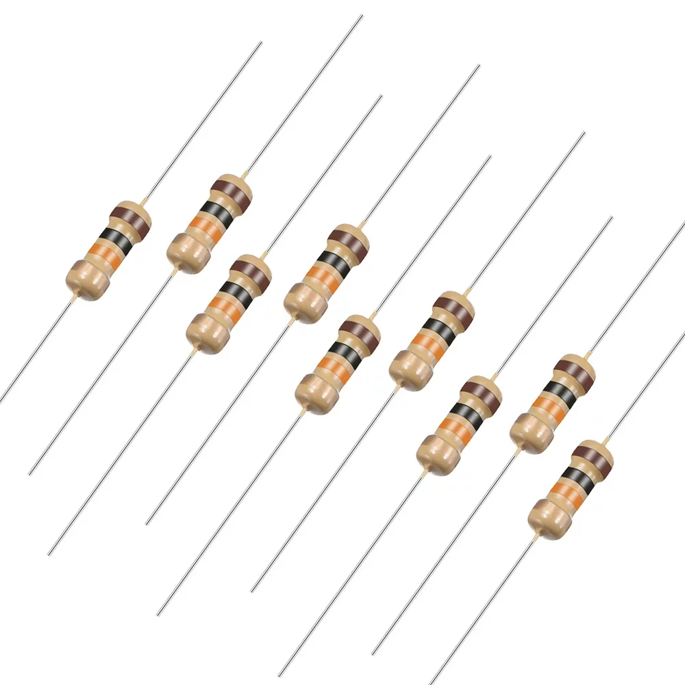
10 Ohm 0.25W Carbon Film Resistor (Pack of 50)
Standard through-hole resistors perfect for bench testing and verifying your multimeter’s resistance measurement accuracy.
Continuity Test and Diode Check Mode
Two extra modes that make a multimeter invaluable on any workbench:
Continuity Mode (Buzzer)
Continuity mode beeps when resistance between the probes is below a threshold (usually 30–50Ω). This is perfect for:
- Checking if a PCB trace is broken
- Verifying jumper wire connections
- Testing fuses (a good fuse beeps; a blown one is silent)
- Confirming solder joints are connected
Diode Mode
In diode mode, the meter applies a small voltage and displays the forward voltage drop. A healthy silicon diode should read approximately 0.6–0.7V forward, while a Schottky diode reads 0.2–0.4V. If the reading is 0.00V (short) or OL (open), the diode is damaged.
You can also test the base-emitter and base-collector junctions of BJT transistors like the popular 2N2222 or BC547 using diode mode.

LCR-T4 LCD Graphical Transistor Tester (R, C, ESR, SCR)
A handy companion to your multimeter — auto-identifies transistors, capacitors, inductors, and ESR. Great for sorting mystery components from your parts bin.
Common Multimeter Mistakes to Avoid
Even experienced makers make these errors — learn them early:
- Wrong probe port for current: Using VΩmA port for >200mA currents will blow the fuse instantly
- Leaving on current mode: Switching from current to voltage without moving the probe blows the fuse
- Measuring resistance in-circuit: Parallel paths give false low readings
- Forgetting to discharge capacitors: Charged caps give wildly incorrect voltage readings (and can shock you)
- Selecting too low a range: Always start at the highest range and work down
- Dead battery: A weak 9V battery in the meter can cause inaccurate resistance readings — check battery health periodically
- Touching probe metal: Finger resistance (around 1MΩ) affects readings in high-resistance measurements
Recommended Tools from Zbotic for Your Test Bench

10CM Male To Female Breadboard Jumper Wires – 40Pcs
Essential for connecting multimeter clips to breadboard circuits during voltage and continuity measurements without soldering.
Frequently Asked Questions
Can I use any multimeter to measure Arduino voltages?
Yes. A basic digital multimeter with a DC voltage range of 0–20V is perfectly adequate for measuring Arduino’s 5V, 3.3V, and analog pin voltages. Just ensure you select the correct range and never touch 230V AC with an inexpensive meter.
What does OL mean on a multimeter display?
OL stands for “Over Limit” — the measured value is higher than the selected range can display. Switch to a higher range immediately. In resistance mode on an open circuit, OL is expected and normal (means no conductive path exists).
How do I measure resistance of a resistor already on a PCB?
You must first power off the circuit and then desolder at least one end of the resistor. Measuring in-circuit gives unreliable results because parallel components affect the reading. Once one lead is free, measure normally across both leads.
Why does my multimeter read a small voltage when measuring resistance?
This happens when there is residual charge in a capacitor or the circuit is still powered. Always discharge capacitors by shorting them through a high-value resistor and confirm power is off before measuring resistance.
Is a ₹300 multimeter good enough for hobby electronics?
Absolutely, for most hobbyist tasks. A basic DT-830B type meter handles 3.5-digit DC/AC voltage, resistance, DC current, continuity and diode testing — everything you need for Arduino and basic circuit work. Upgrade to a CAT-rated auto-range meter only when working with mains AC regularly.
Build a Better Workbench with Zbotic
Ready to start measuring like a pro? Zbotic stocks a wide range of resistors, capacitors, transistors, breadboards, power supplies, and other essentials for Indian makers and electronics students. All orders shipped fast across India.


Add comment