
Table of Contents
- Introduction to the MLX90640
- How Thermal Array Sensors Work
- MLX90640 Specifications
- Hardware Requirements
- Wiring to Arduino / ESP32
- Library Installation and Setup
- Basic Temperature Array Code
- Building the Fever Scanner
- Adding a Display: TFT and OLED Output
- Calibration and Accuracy Tips
- Other Applications Beyond Fever Scanning
- Frequently Asked Questions
- Conclusion
Introduction to the MLX90640
The MLX90640 from Melexis is a 32×24 pixel far-infrared (FIR) thermal array sensor that delivers a complete 768-pixel thermal image over a standard I2C bus. Unlike single-element IR temperature sensors (such as the MLX90614), the MLX90640 gives you a spatial thermal map — essentially a low-resolution thermal camera — at a fraction of the cost of a real infrared camera module.
During the COVID-19 pandemic, MLX90640-based fever scanners became extremely popular in schools, offices, and public buildings as a contactless screening tool. Even beyond that specific application, the sensor opens up dozens of fascinating projects: people counters, fire detection systems, building thermal insulation analysis, wildlife monitoring at night, and even gesture recognition.
In this comprehensive guide, you will learn exactly how the MLX90640 works, how to wire it to an Arduino or ESP32, how to process the 768-pixel temperature array, and how to build a functional fever scanner with a threshold alarm and optional TFT display output.
How Thermal Array Sensors Work
All objects above absolute zero emit infrared radiation proportional to their temperature (Stefan-Boltzmann law). The MLX90640 contains a 32×24 array of thermopile pixels, each of which is a tiny thermal sensor that converts incident infrared radiation into a small voltage. A silicon lens focuses the IR radiation from the scene onto this array, and an integrated signal processor converts all 768 pixel voltages into calibrated temperatures, compensated for the chip’s own ambient temperature and emissivity variations across the array.
The sensor communicates these 768 temperature values (plus metadata) over I2C. The host microcontroller reads a raw data frame, applies a calibration algorithm (provided by Melexis as open-source C code), and obtains a 32×24 array of temperature values in degrees Celsius or Fahrenheit.
Key Technical Concepts
- NETD (Noise Equivalent Temperature Difference): The MLX90640 has a NETD of 0.1K at 1Hz frame rate — meaning it can resolve temperature differences as small as 0.1°C when not averaging over time.
- Emissivity: The sensor assumes a default emissivity of 1.0 (perfect blackbody). Human skin has an emissivity of ~0.98, making the MLX90640 well-suited for body temperature measurement.
- Field of View: Two variants exist — 55°×35° (wide) and 110°×75° (ultra-wide). The 55°×35° version is better for fever screening at 0.5–1.5m distance.
MLX90640 Specifications
| Parameter | Value |
|---|---|
| Pixel array | 32 × 24 = 768 pixels |
| Temperature range (object) | −40°C to +300°C |
| Accuracy | ±1.5°C (0–50°C ambient), ±3°C extended range |
| Thermal resolution | 0.1°C (NETD at 1Hz) |
| Frame rate | 0.5Hz to 64Hz (I2C speed limited) |
| Interface | I2C (up to 1MHz fast-mode) |
| I2C address | 0x33 (default, configurable) |
| Supply voltage | 3.3V (most breakout boards regulate from 5V) |
| Current consumption | ~23mA at 3.3V |
| Field of view options | 55°×35° or 110°×75° |
Hardware Requirements
To build a functional fever scanner, you will need:
- MLX90640 breakout board — the bare IC is SMD-only; use a breakout board with I2C level shifting and 3.3V regulation
- Microcontroller — ESP32 recommended (faster I2C, more RAM for frame buffers, built-in WiFi for remote monitoring); Arduino Uno works but is RAM-constrained
- Display (optional but recommended) — 1.8″ or 2.4″ SPI TFT display for a colorized heatmap, or a 128×64 OLED for a basic grayscale display
- Buzzer or LED — for the fever threshold alarm
- Enclosure — 3D printed or repurposed project box
Important RAM note: Each frame from the MLX90640 requires 768 floats = 3072 bytes of RAM just for the temperature array, plus ~1664 bytes for the calibration data structure. Arduino Uno has only 2KB of RAM total and cannot handle this. Use an Arduino Mega (8KB), Arduino Due (96KB), or preferably an ESP32 (512KB) for comfortable operation.

LM35 Temperature Sensor
Complement your MLX90640 build with an LM35 for ambient reference temperature measurement and offset calibration.
Wiring to Arduino / ESP32
ESP32 Wiring (Recommended)
| MLX90640 Pin | ESP32 Pin |
|---|---|
| VCC | 3.3V |
| GND | GND |
| SDA | GPIO 21 (default SDA) |
| SCL | GPIO 22 (default SCL) |
Add 4.7kΩ pull-up resistors from SDA and SCL to 3.3V if your breakout board does not include them. Most breakout boards already include pull-ups — check before adding external ones.
Arduino Mega Wiring
| MLX90640 Pin | Arduino Mega Pin |
|---|---|
| VCC | 5V (board regulates to 3.3V internally) |
| GND | GND |
| SDA | Pin 20 (SDA) |
| SCL | Pin 21 (SCL) |
Library Installation and Setup
The recommended library is the Adafruit MLX90640 library, available through the Arduino Library Manager. It wraps Melexis’s official open-source calibration code and provides a simple API:
- Open Arduino IDE → Sketch → Include Library → Manage Libraries
- Search for “MLX90640” and install “Adafruit MLX90640”
- Also install “Adafruit BusIO” if prompted
For ESP-IDF or MicroPython users, Melexis’s official C API (MIT licensed) and community MicroPython ports are available on GitHub.
Basic Temperature Array Code
#include <Wire.h>
#include <Adafruit_MLX90640.h>

Adafruit_MLX90640 mlx;
float frame[32 * 24]; // 768 pixel temperature array

void setup() {
  Serial.begin(115200);
  while (!Serial) delay(10);

  Serial.println("MLX90640 Thermal Camera");

  if (!mlx.begin(MLX90640_I2CADDR_DEFAULT, &Wire)) {
    Serial.println("MLX90640 not found! Check wiring.");
    while (1) delay(10);
  }

  // Set mode and resolution
  mlx.setMode(MLX90640_CHESS);          // Chess pattern for better accuracy
  mlx.setResolution(MLX90640_ADC_18BIT); // 18-bit ADC resolution
  mlx.setRefreshRate(MLX90640_2_HZ);    // 2 frames per second

  Serial.print("Serial number: ");
  Serial.print(mlx.serialNumber[0], HEX);
  Serial.print(mlx.serialNumber[1], HEX);
  Serial.println(mlx.serialNumber[2], HEX);
}

void loop() {
  if (mlx.getFrame(frame) != 0) {
    Serial.println("Frame failed");
    return;
  }

  // Find maximum temperature in the frame
  float maxTemp = -273.0;
  float minTemp = 999.0;
  int maxPixel = 0;

  for (int i = 0; i  maxTemp) {
      maxTemp = frame[i];
      maxPixel = i;
    }
    if (frame[i] < minTemp) minTemp = frame[i];
  }

  Serial.print("Max temp: "); Serial.print(maxTemp); Serial.println(" C");
  Serial.print("Min temp: "); Serial.print(minTemp); Serial.println(" C");
  Serial.print("Hot spot at pixel: "); Serial.println(maxPixel);

  // Print full thermal image to Serial (CSV)
  for (int y = 0; y < 24; y++) {
    for (int x = 0; x < 32; x++) {
      Serial.print(frame[y * 32 + x], 1);
      if (x < 31) Serial.print(",");
    }
    Serial.println();
  }
  Serial.println("---");
}
Building the Fever Scanner
A fever scanner uses the thermal array to detect the maximum temperature in the frame, applies an emissivity and ambient offset correction, and compares it against a fever threshold (typically 37.5°C skin temperature, which corresponds to approximately 38.0°C core body temperature).
Key Design Considerations
- Distance: Measure at a fixed distance of 50–100cm. The sensor’s 55°×35° FOV covers a face at this distance in 8–10 pixels. Consistency in distance is critical.
- Ambient correction: The MLX90640’s internal compensation automatically accounts for its own ambient temperature. However, environmental factors (drafts, nearby heat sources) still affect readings.
- Emissivity offset: Human forehead skin reads 0.5–1.5°C lower than true body temperature on an infrared sensor. Apply a fixed offset empirically calibrated against a reference thermometer.
- Measurement zone: Focus on the central 8×6 pixel region of the frame (the forehead area) rather than the absolute maximum, which might be a hot object in the background.
#include <Wire.h>
#include <Adafruit_MLX90640.h>

Adafruit_MLX90640 mlx;
float frame[32 * 24];

const int BUZZER_PIN = 4;
const float FEVER_THRESHOLD = 37.5;  // degrees Celsius
const float OFFSET = 1.2;            // Empirical offset: skin → core body temp

void setup() {
  Serial.begin(115200);
  pinMode(BUZZER_PIN, OUTPUT);

  if (!mlx.begin(MLX90640_I2CADDR_DEFAULT, &Wire)) {
    Serial.println("Sensor not found!");
    while (1);
  }

  mlx.setMode(MLX90640_CHESS);
  mlx.setResolution(MLX90640_ADC_18BIT);
  mlx.setRefreshRate(MLX90640_2_HZ);

  Serial.println("Fever Scanner Ready");
  Serial.println("Position subject 60-80cm from sensor");
}

float measureCentralZone() {
  // Average the central 8x6 pixel region (forehead area)
  float sum = 0;
  int count = 0;
  for (int y = 9; y < 15; y++) {      // Rows 9-14 (central 6 rows)
    for (int x = 12; x  ");

  if (bodyTemp >= FEVER_THRESHOLD) {
    Serial.println("FEVER DETECTED!");
    // Sound buzzer: 3 short beeps
    for (int i = 0; i < 3; i++) {
      digitalWrite(BUZZER_PIN, HIGH);
      delay(200);
      digitalWrite(BUZZER_PIN, LOW);
      delay(100);
    }
  } else {
    Serial.println("Normal");
    // Single confirmation beep
    digitalWrite(BUZZER_PIN, HIGH);
    delay(50);
    digitalWrite(BUZZER_PIN, LOW);
  }

  delay(1000);
}
DHT20 SIP Temperature & Humidity Sensor
Use the DHT20 to measure ambient temperature and humidity for environmental compensation in your MLX90640 fever scanner project.
Adding a Display: TFT and OLED Output
A colorized heatmap on a TFT display makes the fever scanner far more intuitive for users. The technique is to map each pixel’s temperature to a color on a rainbow gradient (blue = cold, green = medium, red = hot) and draw scaled rectangles on the display.
Color Mapping Function
// Convert temperature to 16-bit RGB565 color (blue → green → red)
uint16_t tempToColor(float temp, float minT, float maxT) {
  float ratio = (temp - minT) / (maxT - minT);
  ratio = constrain(ratio, 0.0, 1.0);

  uint8_t r = 0, g = 0, b = 0;
  if (ratio < 0.25) {
    b = 255;
    g = (uint8_t)(ratio * 4 * 255);
  } else if (ratio < 0.5) {
    g = 255;
    b = (uint8_t)((0.5 - ratio) * 4 * 255);
  } else if (ratio > 3);
}

// Draw thermal image on TFT (each pixel = 5x5 rectangle)
void drawThermalImage(Adafruit_ST7735* tft, float* frame, float minT, float maxT) {
  for (int y = 0; y < 24; y++) {
    for (int x = 0; x fillRect(x * 5, y * 5, 5, 5, color);
    }
  }
}
Calibration and Accuracy Tips
The MLX90640’s ±1.5°C factory accuracy is adequate for fever screening (the WHO definition of fever is ≥37.5°C). Here are steps to maximize accuracy in your build:
- Warm-up time: Allow 30 seconds after power-on before taking measurements. The sensor’s internal calibration stabilizes after a few frames.
- Emissivity offset calibration: Compare MLX90640 forehead readings against a calibrated clinical ear thermometer on 10+ subjects. Compute the average difference — this is your
OFFSETconstant. - Fixed measurement distance: Mount the sensor at a fixed height (forehead level) with a physical distance marker (tape on the floor at 60cm). Inconsistent distance is the largest source of measurement variation.
- Avoid drafts: Air conditioning vents directly above the measurement area can cool the forehead by 0.5–1.0°C, causing false negatives.
- Frame averaging: Average 3–5 consecutive frames before reporting a result. This reduces the effect of pixel-to-pixel noise (NETD).
Other Applications Beyond Fever Scanning
Building Thermal Inspection
Walk along exterior walls holding the MLX90640 on a Raspberry Pi with a touchscreen. Cold spots indicate missing insulation or air leaks. The 32×24 pixel resolution is sufficient to identify problem areas, even if you need a professional thermal camera for documentation.
People Counter
Mount the sensor above a doorway pointing straight down. Human bodies produce a distinctive thermal signature that stands out from the background. Count entries and exits by tracking thermal blobs crossing an imaginary line in the frame. Accuracy reaches 95%+ in controlled environments.
Fire and Overheating Detection
Monitor server racks, electrical panels, or manufacturing equipment for hotspots. Set an alarm when any pixel exceeds 60°C. The wide field of view covers an entire server rack from 2 meters away.
Wildlife Night Monitoring
Attach the sensor to a Raspberry Pi Zero in a weatherproof enclosure. Animals appear as bright warm spots against a cool background at night. Trigger a camera when a thermal blob of human-like size and temperature enters the frame.
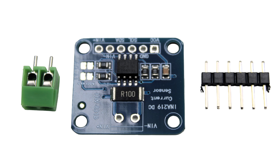
INA219 I2C Current/Power Monitoring Module
Monitor the power consumption of your MLX90640 fever scanner system with the INA219 current sensor — great for battery-powered enclosures.
Frequently Asked Questions
Q: Can I use the MLX90640 with Arduino Uno?
A: Technically yes, but practical operation is extremely difficult due to Arduino Uno’s 2KB RAM limit. The frame buffer alone requires 3KB. Use an Arduino Mega (8KB RAM) as the minimum, or ideally an ESP32 (512KB RAM) which handles the full frame plus display output with ease.
Q: What is the maximum I2C speed for the MLX90640?
A: The sensor supports I2C Fast Mode (400kHz) and Fast Mode Plus (1MHz). Using 400kHz gives about 3–4 frames per second; 1MHz allows up to 8 frames per second. Set Wire.setClock(400000) or Wire.setClock(1000000) before initializing the sensor.
Q: Is the MLX90640 fever scanner medically certified?
A: No. DIY fever scanners built with the MLX90640 are not medical devices and should not be used as a substitute for clinical diagnosis. They are suitable as a preliminary screening tool only. For medical-grade applications, use certified non-contact thermometers or thermal cameras with IEC 80601-2-59 certification.
Q: Can I run two MLX90640 sensors on the same I2C bus?
A: Yes. The MLX90640’s I2C address (0x33 by default) can be changed to 0x32, 0x34, or 0x35 by programming the EEPROM via a dedicated command. This allows up to 4 sensors on the same bus. Alternatively, use an I2C multiplexer (TCA9548A) for more sensors.
Q: My readings seem consistently 2-3°C too low — what is wrong?
A: This is almost always the emissivity offset issue. The sensor is calibrated for emissivity = 1.0 (perfect blackbody). Human skin emissivity is ~0.98, and the skin surface temperature on the forehead is 1–2°C below core body temperature. Add a calibrated offset (typically +1.0 to +2.0°C) determined by comparison with a reference thermometer.
Conclusion
The MLX90640 thermal array sensor is one of the most capable and exciting sensor modules available for Arduino and ESP32 projects. With its 32×24 pixel thermal image, ±1.5°C accuracy, standard I2C interface, and accessible price point, it enables projects that would have required expensive professional equipment just a few years ago.
Building a fever scanner is an excellent introduction to the sensor — it is a real, practical application with immediate utility. But the same hardware can pivot to building inspection, people counting, fire detection, or wildlife monitoring with minimal code changes. The common thread is the ability to see temperature across a scene, which opens creative possibilities far beyond what any single-point temperature sensor can achieve.
Start with the basic temperature array example, visualize the output in the Serial Plotter or a Python heatmap script, then build up to the fever scanner with display and alarm. Once you see your first thermal image on the TFT screen, you will immediately start imagining the next application.


Add comment