
You have wired up your sensor, uploaded your sketch, and opened the Serial Monitor — only to see values jumping randomly by 10–50 units every reading. Your temperature sensor fluctuates 3°C in a second. Your soil moisture sensor oscillates between 45% and 67% in still air. Your current sensor shows 0.3A even when nothing is connected.
Noisy sensor readings are one of the most common problems in Arduino projects, and fixing them requires understanding both the hardware and software causes. This troubleshooting guide covers every practical technique — from a 10-cent capacitor to a full Kalman filter implementation — so you can choose the right fix for your specific situation.
1. Why Sensors Produce Noisy Readings
Noise in sensor readings comes from multiple sources, and understanding the source helps you pick the most effective fix:
ADC Quantization Noise
Arduino’s 10-bit ADC divides 0–5V into 1024 steps (~4.88 mV per step). Any measurement uncertainty within one ADC step appears as a ±1 LSB (Least Significant Bit) flicker. With the LM35 at 10 mV/°C, this means ±0.49°C noise is inherent to the ADC even with a perfect sensor.
Power Supply Noise
The ADC reference is VCC. If your power supply has ripple (from a cheap USB charger, a motor sharing the rail, or a switching regulator without filtering), the ADC reference fluctuates, making every reading appear noisy even when the sensor is measuring something perfectly stable.
Electromagnetic Interference (EMI)
Motors, relay coils, PWM signals, and even long unshielded wires pick up high-frequency electrical noise and inject it into your sensor signal lines. This is very common when sensors share a PCB or enclosure with motors.
Sensor Internal Noise
Some sensors have inherently noisy outputs. The ACS712 current sensor has a noise floor of ~40–50 mV (equivalent to 0.3–0.8 A of apparent noise at the 5A version). Resistive soil moisture sensors are especially noisy due to electrochemical effects.
Mechanical Vibration
Accelerometers, pressure sensors, and load cells can pick up vibration from nearby machinery. This appears as rapid fluctuations at the vibration frequency.
2. Diagnose Before You Filter
Filtering masks symptoms. Before applying a software filter, identify what type of noise you have:
- Disconnect the sensor and tie the ADC pin to GND. If readings are still noisy, the problem is ADC/power supply noise.
- Replace the sensor with a stable voltage from a voltage divider. If noise disappears, the sensor itself is the source.
- Disconnect motors/relays. If noise disappears, you have EMI from inductive loads.
- Check the noise pattern: Random scatter = Gaussian noise (averaging works well). Occasional spikes = impulse noise (median filter works best). Regular oscillation = pick up from a specific frequency source (hardware filter at that frequency).
3. Hardware Fixes: The First Line of Defence
Hardware fixes reduce noise before it reaches the ADC, which is always more effective than software filtering on corrupted data.
Decoupling Capacitors
Add a 100 nF ceramic capacitor (and optionally a 10 µF electrolytic) between the sensor’s VCC and GND pins, placed as close to the sensor as possible. This filters high-frequency power supply noise that the sensor’s circuits are sensitive to.
Sensor VCC ---+---[100nF to GND]
              +---[10µF to GND]  (electrolytic, + toward VCC)
              |
              [Sensor]
RC Low-Pass Filter on Analog Input
A resistor-capacitor (RC) filter on the analog signal line is the simplest and most effective hardware fix for high-frequency noise on analog sensor outputs. The cutoff frequency is:
fc = 1 / (2 * π * R * C)

Example: R=10kΩ, C=100nF → fc = 159 Hz

Wiring:
Sensor Output ---[10kΩ]---+--- Arduino A0
                          |
                        [100nF]
                          |
                         GND
Choose the cutoff frequency based on how fast your measured quantity actually changes. A temperature sensor only needs 1–10 Hz bandwidth; an accelerometer measuring vibration might need 100+ Hz.
Use the Internal 1.1V ADC Reference
For sensors with small signal range, switch Arduino’s ADC reference to the internal 1.1V bandgap reference. This is much more stable than VCC:
analogReference(INTERNAL); // 1.1V reference on Uno/Nano
// Now 10-bit ADC resolution = 1.1V / 1024 = 1.07 mV/step
// vs 4.88 mV/step at 5V — 4.6x better resolution
Twisted Pair and Shielding
For sensors with long wires (thermocouples, load cells), use twisted pair wires (or shielded cable) to reject differential EMI. Ground the shield at one end only to avoid ground loops.

DS18B20 Programmable Resolution Temperature Sensor
Digital 1-Wire sensor with built-in ADC — inherently immune to analog noise on signal lines. Switching from LM35 to DS18B20 often eliminates noisy readings entirely without any filtering.
4. Simple Averaging Filter
The simplest software filter: take N readings in rapid succession and average them. This reduces Gaussian (random) noise by a factor of √N. Taking 16 samples reduces noise by 4x; 64 samples by 8x.
int readAveraged(int pin, int samples) {
  long sum = 0;
  for (int i = 0; i < samples; i++) {
    sum += analogRead(pin);
    delayMicroseconds(100); // small gap between reads helps
  }
  return sum / samples;
}

void loop() {
  int smoothed = readAveraged(A0, 16);
  float voltage = smoothed * (5.0 / 1023.0);
  Serial.println(voltage);
  delay(500);
}
Limitation: All N readings are taken at the same moment, so this reduces measurement-to-measurement random noise but does not smooth readings over time. It also cannot reject outliers (spikes) — a single 800-unit spike pulls the average significantly.
5. Moving Average (Rolling Average) Filter
A moving average maintains a buffer of the last N readings and returns their mean. Unlike simple averaging, new readings are added over time, creating temporal smoothing.
#define WINDOW_SIZE 10

int readings[WINDOW_SIZE];
int readIndex = 0;
long total = 0;

void setup() {
  Serial.begin(9600);
  memset(readings, 0, sizeof(readings));
}

void loop() {
  // Subtract oldest reading
  total -= readings[readIndex];
  // Read new value
  readings[readIndex] = analogRead(A0);
  // Add new reading
  total += readings[readIndex];
  // Advance index
  readIndex = (readIndex + 1) % WINDOW_SIZE;
  // Calculate average
  int average = total / WINDOW_SIZE;

  Serial.println(average);
  delay(50);
}
Window size trade-off: Larger window = more smoothing but slower response to real changes. For temperature (slow-changing), use window 20–50. For distance sensors (faster-changing), use window 5–10.
6. Median Filter: Best for Spike Rejection
The median filter is the most powerful tool against impulse noise (sudden spikes). Instead of averaging, it takes N readings and returns the middle value. A single spike — no matter how large — cannot affect the median if it appears in less than half the readings.
#define MEDIAN_SIZE 7

int medianFilter(int pin) {
  int buf[MEDIAN_SIZE];
  // Collect samples
  for (int i = 0; i < MEDIAN_SIZE; i++) {
    buf[i] = analogRead(pin);
    delay(2);
  }
  // Simple insertion sort
  for (int i = 1; i < MEDIAN_SIZE; i++) {
    int key = buf[i];
    int j = i - 1;
    while (j >= 0 && buf[j] > key) {
      buf[j + 1] = buf[j];
      j--;
    }
    buf[j + 1] = key;
  }
  // Return middle element
  return buf[MEDIAN_SIZE / 2];
}

void loop() {
  int filtered = medianFilter(A0);
  Serial.println(filtered);
  delay(100);
}
Use an odd number for MEDIAN_SIZE (5, 7, or 9 are common). Median filters are especially good for ultrasonic sensors (which occasionally give bogus short-distance readings) and soil moisture sensors (which have occasional extreme spikes).
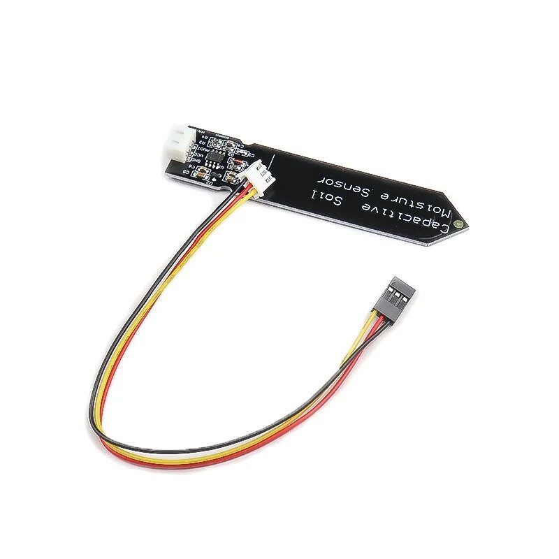
Capacitive Soil Moisture Sensor
Capacitive design eliminates the resistive noise and corrosion of resistive sensors. Pair with median filtering in Arduino code for stable, reliable soil moisture readings.
7. Exponential Moving Average (EMA)
The EMA (also called a first-order IIR filter) is memory-efficient: it requires only one stored value instead of a buffer. It weights recent readings more heavily than old ones, making it responsive while still smoothing noise.
// Alpha controls smoothing: higher = more responsive, lower = more smooth
// Alpha range: 0.0 (infinite memory) to 1.0 (no filtering)
const float ALPHA = 0.1;

float ema = 0;
bool initialized = false;

void loop() {
  int raw = analogRead(A0);
  if (!initialized) {
    ema = raw;
    initialized = true;
  } else {
    ema = ALPHA * raw + (1.0 - ALPHA) * ema;
  }
  Serial.println(ema);
  delay(50);
}
Choosing Alpha:
- Alpha = 0.5: Aggressive filtering, fast response (recent reading gets 50% weight)
- Alpha = 0.1: Moderate filtering (recent reading gets 10% weight, equivalent to ~10-sample average)
- Alpha = 0.02: Heavy filtering (equivalent to ~50-sample average)
EMA is excellent for temperature, pressure, and humidity monitoring where real values change slowly. It is not ideal for fast-moving measurements like distance from an ultrasonic sensor.
8. Kalman Filter for Arduino
The Kalman filter is the most sophisticated option. It is an optimal estimator that combines a mathematical model of how the system evolves with the noisy measurement to produce the best possible estimate of the true state. For 1D sensor filtering, a simplified scalar Kalman filter is easy to implement.
// Simple 1D Kalman filter
struct KalmanFilter {
  float Q; // Process noise variance (how fast the true value changes)
  float R; // Measurement noise variance (sensor noise level)
  float P; // Estimation error covariance
  float K; // Kalman gain
  float X; // Current state estimate

  KalmanFilter(float q, float r) : Q(q), R(r), P(1.0), K(0), X(0) {}

  float update(float measurement) {
    // Prediction step
    P = P + Q;
    // Update step
    K = P / (P + R);
    X = X + K * (measurement - X);
    P = (1 - K) * P;
    return X;
  }
};

// Q=0.1 (slow changing temp), R=10 (noisy ADC)
KalmanFilter kf(0.1, 10.0);

void setup() { Serial.begin(9600); }

void loop() {
  float raw = analogRead(A0);
  float filtered = kf.update(raw);
  Serial.print(raw); Serial.print(","); Serial.println(filtered);
  delay(50);
}
Tuning Q and R:
- Increase R if the sensor is very noisy (reduces responsiveness but smoother).
- Increase Q if the measured value changes rapidly (more responsive, less smooth).
- Start with Q=0.1 and R=1, then adjust based on observed behavior.

LM35 Temperature Sensors
Classic analog temperature sensor that benefits greatly from EMA or Kalman filtering — the Kalman filter can achieve stable 0.1°C readings from this noisy analog sensor.
9. Which Filter Should You Use?
| Filter | Best For | RAM Usage | CPU Cost | Spike Rejection |
|---|---|---|---|---|
| Simple Average | Quick noise reduction at read time | None | Low | Poor |
| Moving Average | Temporal smoothing of slow signals | N × 2 bytes | Low | Poor |
| Median Filter | Spike/outlier rejection | N × 2 bytes | Medium | Excellent |
| EMA | Memory-efficient continuous smoothing | 4 bytes | Very low | Fair |
| Kalman Filter | Optimal estimate with model knowledge | ~20 bytes | Medium | Good |
Practical recommendation for most projects: Combine a median filter (7 samples) with an EMA (alpha=0.1) for robust, spike-resistant, smooth output with minimal code.
10. Fixes for Specific Sensor Types
DHT11 / DHT20 — Occasional “nan” or 0 Readings
These are timing-sensitive sensors. The most common fix: add a 10 kΩ pull-up resistor on the data line, increase the delay between readings to at least 2 seconds (DHT11) or 0.5 seconds (DHT20), and discard any reading that is outside the physically plausible range (temperature < -40°C or > 85°C).
Ultrasonic HC-SR04 — Occasional 0 cm or 4 m Readings
Ultrasonic sensors occasionally miss the echo or pick up stray reflections, giving bogus 0 or out-of-range readings. Apply a median filter (7 samples) and add bounds checking:
if (distance < 2 || distance > 400) distance = previousDistance;ACS712 Current Sensor — Noise Floor
The ACS712 has inherent noise. Use 64-sample averaging at zero current to calibrate the zero point, and apply EMA (alpha=0.05) for smooth current readings. For small currents (<1A), consider the INA219 which uses a precision shunt and I2C interface for much lower noise.
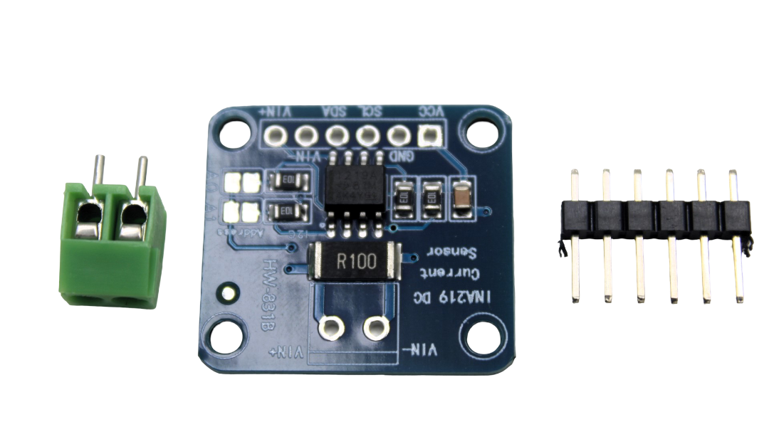
CJMCU-219 INA219 I2C Bi-directional Current/Power Monitoring Module
Digital current sensing with 12-bit resolution and I2C interface — no analog noise issues. Built-in calibration registers give 1mA resolution without any filtering code needed.
BME280 / BMP280 — Altitude Fluctuations
Atmospheric pressure fluctuates naturally by ±0.3 hPa in normal conditions, giving ±2.5 m apparent altitude change. Use a long-window EMA (alpha=0.01–0.05) for altitude display. Do not confuse noise with the real pressure changes that happen as you move around.
FAQ: Noisy Sensor Readings
Why do my sensor readings fluctuate even when nothing is happening?
The most common causes are: (1) Power supply noise — check if powering from a phone charger vs a regulated lab supply makes a difference. (2) ADC inherent quantization — even a perfect stable voltage will show ±1 LSB variation. (3) Sensor self-heating — some sensors heat up after power-on and take 2–5 minutes to stabilize. (4) Floating input — if any wire is disconnected or the sensor data line has no pull-up/pull-down, the ADC reads random floating voltages. Always check the wiring first.
What is the best filter for DHT11 sensor readings in Arduino?
DHT11 readings are already digital (not analog noise), so ADC filtering does not help. The main issues are: (1) Occasional failed reads returning 0 or NaN — fix by checking return value and discarding invalid readings. (2) Slow sensor drift — use a 5-sample simple average with 2-second intervals between reads. (3) ±2°C sensor inaccuracy — this is systematic error requiring calibration, not filtering. For projects needing better data quality, switching to DHT20 or BME280 is more effective than any filter.
How many samples should I take for averaging to reduce noise?
For Gaussian noise (random fluctuations), noise is reduced by √N where N is the number of samples. 4 samples halves the noise; 16 samples quarters it; 64 samples reduces it by 8x. Beyond 64 samples the returns diminish and you add latency. In practice, 8–16 samples is a good balance for most Arduino ADC applications. For impulse noise (spikes), averaging is ineffective — use a median filter instead.
My readings jump by 100+ counts randomly — what filter handles this?
Large random jumps are impulse noise (spikes), typically caused by EMI from nearby motors, relays, or power electronics. The median filter is designed exactly for this. Use a 7-sample median filter — it will completely reject single spikes regardless of magnitude. Additionally, add a 100nF decoupling capacitor near the sensor and ensure motor drivers have flyback diodes on their relay coils. If the spikes coincide with PWM output or relay switching, that is your interference source.
Does filtering slow down my Arduino sensor readings?
Simple averaging and EMA have minimal CPU overhead. A moving average or median filter with N=7–10 samples adds microseconds of computation and a few bytes of RAM. The Kalman filter adds about 5–10 microseconds of floating point math. The real latency consideration is sample collection: if you take 16 samples with 2ms delay between each, you add 32ms of latency per reading. For most sensor applications (temperature, humidity, soil moisture), this is completely acceptable. For fast applications (ultrasonic distance in a moving robot), use the EMA which processes one sample at a time with no added latency.
Stop Fighting Noise — Fix It Properly
Noisy sensor readings waste your debugging time and make your projects unreliable. With the hardware and software techniques in this guide, you have everything needed to achieve stable, accurate readings from any sensor — from a cheap LM35 to a precision load cell.
Start with hardware fixes (decoupling capacitors, RC filter), then apply the right software filter for your noise type. For most projects, combining a median filter and EMA gives excellent results with minimal code.
Explore Zbotic’s range of quality sensors, many with built-in digital interfaces that sidestep analog noise entirely.


Add comment