
Did you know the ESP32 has a built-in hall effect sensor right inside the chip? The ESP32 hall sensor can detect the presence and direction of magnetic fields without any external components — making it a powerful tool for proximity detection, RPM measurement, position sensing, and anti-tamper applications. In this complete guide, you will learn how to read the ESP32’s internal hall effect sensor, understand its limitations, and build practical IoT projects around it.
What is a Hall Effect Sensor?
The Hall effect, discovered by physicist Edwin Hall in 1879, describes the phenomenon where a voltage difference appears across a conductor perpendicular to both an electric current and a magnetic field. Modern Hall effect sensors use this principle to detect magnetic fields with high sensitivity and reliability.
Hall effect sensors are everywhere in modern electronics:
- Smartphone flip covers that auto-lock the screen use tiny Hall sensors to detect the magnet in the cover
- Electric motors use Hall sensors for commutation (detecting rotor position)
- Car speedometers count wheel rotations using a ring magnet and Hall sensor
- Door and window sensors in alarm systems
- Contactless current sensing
- Geomagnetic compasses (different from Hall sensors but similar principle)
ESP32’s Built-In Hall Effect Sensor
The ESP32 chip (specifically the Xtensa LX6 SoC) includes a built-in Hall effect sensor implemented in the same silicon as the chip itself. This is the same ADC hardware used for the touch sensor subsystem. The ESP32’s hall sensor measures the magnetic field perpendicular to the top surface of the chip.
Key specifications of the ESP32 internal hall sensor:
| Parameter | Value |
|---|---|
| Measurement type | Relative magnetic flux density |
| Output range | Approximately -70 to +70 (relative units) |
| Baseline (no magnet) | Typically -30 to +30 (varies per chip) |
| Update rate | Up to 1000 readings/second |
| Pins used internally | GPIO 36 and GPIO 39 (SVN, SVP) |
| Power | Uses the ADC1 subsystem |
Important: Because the hall sensor uses GPIO 36 and GPIO 39 internally, you should not use these pins for other ADC purposes while reading the hall sensor. On most ESP32 development boards, GPIO 36 (VP) and GPIO 39 (VN) are available as input pins, but connecting them to external circuits may interfere with hall sensor readings.
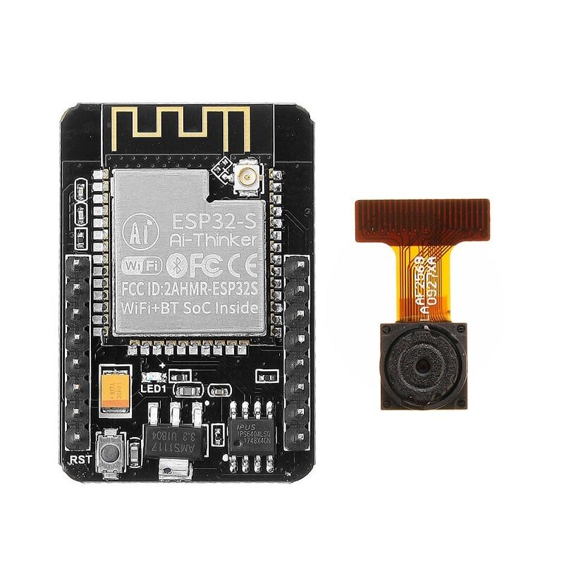
Ai Thinker ESP32-CAM Development Board WiFi+Bluetooth
The ESP32-CAM also includes the built-in hall sensor. Pair magnetic detection with camera triggering to build a smart security system that photographs when a magnet is moved.
Reading the Hall Sensor in Arduino IDE
Reading the ESP32’s built-in hall sensor in Arduino IDE is surprisingly simple — just one function call:
void setup() {
  Serial.begin(115200);
  Serial.println("ESP32 Hall Effect Sensor Demo");
}

void loop() {
  int hallValue = hallRead();
  Serial.printf("Hall Sensor: %dn", hallValue);
  delay(100);
}
The hallRead() function is built into the ESP32 Arduino core — no library installation required. Upload this sketch, open the Serial Monitor at 115200 baud, and observe the baseline reading with no magnet nearby. Then bring a strong neodymium magnet close to the top surface of the ESP32 chip and watch the values change dramatically.
Improved Reading with Averaging
The raw hall sensor output can be noisy. For more stable readings, average multiple samples:
#define SAMPLES 32

int readHallAveraged() {
  long sum = 0;
  for (int i = 0; i < SAMPLES; i++) {
    sum += hallRead();
    delayMicroseconds(100);
  }
  return sum / SAMPLES;
}

void setup() {
  Serial.begin(115200);
}

void loop() {
  int hall = readHallAveraged();
  Serial.printf("Hall (averaged): %dn", hall);
  delay(250);
}
This averaging approach reduces noise by approximately sqrt(32) ≈ 5.7x, giving you much cleaner readings for precision applications.
Interpreting Sensor Values
The hall sensor returns relative values, not calibrated magnetic flux density in milliTesla. Here is how to interpret them:
- Baseline (~0): No significant magnetic field present (Earth’s field is detected but is very weak)
- Positive values (e.g. +40 to +70): North pole of magnet facing the chip’s top surface
- Negative values (e.g. -40 to -70): South pole of magnet facing the chip’s top surface
- Values near maximum/minimum: Strong magnet very close to chip
To detect magnet presence with a threshold:
#define MAGNET_THRESHOLD 40
#define BASELINE_SAMPLES 100

int baseline;

void setup() {
  Serial.begin(115200);

  // Calibrate baseline (no magnet during calibration)
  long sum = 0;
  for (int i = 0; i < BASELINE_SAMPLES; i++) {
    sum += hallRead();
    delay(10);
  }
  baseline = sum / BASELINE_SAMPLES;
  Serial.printf("Calibrated baseline: %dn", baseline);
}

void loop() {
  int hall = hallRead();
  int delta = abs(hall - baseline);

  if (delta > MAGNET_THRESHOLD) {
    Serial.printf("MAGNET DETECTED! Delta=%d, Value=%dn", delta, hall);
  } else {
    Serial.printf("No magnet. Delta=%dn", delta);
  }
  delay(200);
}
Practical Project Ideas
1. Magnetic Door/Window Sensor (Anti-Tamper)
Attach a small neodymium magnet to a door or window frame, with the ESP32 on the door/window itself. When closed, the magnet is close to the ESP32 and gives a high delta reading. When opened, the delta drops below the threshold. Send an MQTT alert or push notification on opening.
2. RPM Counter for Motors and Fans
Attach a small magnet to a rotating shaft. Each time the magnet passes over the ESP32, the hall reading spikes. Count these pulses per second to calculate RPM. This works up to several hundred RPM with the built-in sensor (faster requires external sensors).
unsigned long lastPulse = 0;
int rpm = 0;
int pulseCount = 0;

void loop() {
  int hall = hallRead();
  if (abs(hall - baseline) > MAGNET_THRESHOLD) {
    if (millis() - lastPulse > 50) { // Debounce 50ms
      pulseCount++;
      lastPulse = millis();
    }
  }
  // Calculate RPM every second
  static unsigned long lastCalc = 0;
  if (millis() - lastCalc >= 1000) {
    rpm = pulseCount * 60;
    pulseCount = 0;
    lastCalc = millis();
    Serial.printf("RPM: %dn", rpm);
  }
}
3. Compass / Orientation Detection
While not precise enough for navigation, you can detect rough orientation relative to Earth’s magnetic field. Rotate the ESP32 module and map the hall readings to cardinal directions. Combine with an accelerometer for a basic tilt-compensated compass.
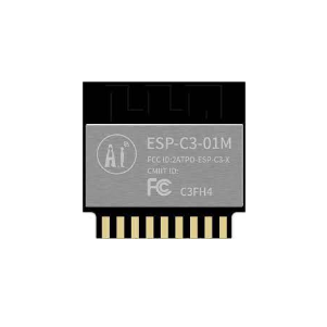
Ai Thinker ESP32-C3-01M Wi-Fi + BLE Module
A compact, cost-effective ESP32 variant for embedding into custom hardware. Note: ESP32-C3 does NOT have a built-in hall sensor — use the original ESP32 for hall sensing.
Limitations and When to Use External Sensors
The ESP32 internal hall sensor has significant limitations you must understand before building a production system:
- No calibrated output: Values are chip-specific and vary between ESP32 chips. You cannot compare absolute readings between different modules.
- Low sensitivity: It detects strong magnets (neodymium, ferrite) at close range (under ~3cm). It cannot measure Earth’s geomagnetic field for compass use reliably.
- High noise: Baseline noise of ±5 units requires averaging and generous thresholds.
- Single axis: Only measures the component of the magnetic field perpendicular to the chip’s top surface.
- Deprecated in newer chips: The
hallRead()function is NOT available on ESP32-S2, ESP32-S3, ESP32-C3, or ESP32-H2. It only works on the original ESP32 (Xtensa LX6 dual-core).
Working with External Hall Effect Sensors
For precision applications requiring calibrated mT measurements, directional sensing, or compatibility with newer ESP32 variants, use dedicated external Hall effect ICs. Popular options available in India:
- A3144 (digital): Simple ON/OFF output, triggers at ~350 Gauss. Used in door sensors, motor position detection. Connects to any GPIO.
- SS49E (linear analog): Continuous voltage output proportional to field strength. Read with ADC for precise measurements.
- AH49E: Similar to SS49E, omnipolar (responds to both poles). Very common in India.
- MLX90393 (SPI/I2C): Professional 3-axis magnetometer with 16-bit resolution. Used in robotics and navigation.
Connecting a digital Hall sensor (A3144) to ESP32:
#define HALL_PIN 34  // Input-only GPIO

void setup() {
  Serial.begin(115200);
  pinMode(HALL_PIN, INPUT_PULLUP);
  // A3144 is open-collector: LOW = magnet detected
}

void loop() {
  bool magnetDetected = !digitalRead(HALL_PIN); // Inverted
  Serial.println(magnetDetected ? "MAGNET DETECTED" : "No magnet");
  delay(100);
}

LM35 Temperature Sensor
The LM35 is an analog temperature sensor that demonstrates the same ADC reading approach used for the ESP32 hall sensor — a great pairing for multi-sensor IoT projects.
Frequently Asked Questions
Does the ESP32-S3 or ESP32-C3 have a hall effect sensor?
No. The built-in hall effect sensor and the hallRead() function are only available on the original ESP32 (dual-core Xtensa LX6). The ESP32-S2, S3, C3, C6, and H2 variants do NOT include this feature. If you need hall sensing on these newer chips, use an external sensor like the A3144 or SS49E connected to a GPIO or ADC pin.
How close does a magnet need to be for the ESP32 to detect it?
A small 5×3mm neodymium N52 magnet can be detected reliably within ~15–20mm. A larger 10×5mm magnet extends this to ~30mm. The sensitivity drops off rapidly with distance (inverse cube law). The magnet must be oriented so its field line passes through the top surface of the ESP32 chip — the sensor is only sensitive to one axis.
Can I use ESP32 hall sensor to detect the Earth’s magnetic field for a compass?
In theory yes, but in practice no. Earth’s magnetic field (25–65 μT) is at the very lower limit of the ESP32 hall sensor’s detection capability, and the noise level typically exceeds the signal. Dedicated magnetometer ICs like the HMC5883L (QMC5883L) or LIS3MDL are required for reliable compass applications. These connect via I2C and cost very little — far better than struggling with the noisy built-in sensor.
Why does my ESP32 hall reading drift over time?
Thermal drift is the most common cause. As the ESP32 chip heats up during operation (especially when Wi-Fi is active), the baseline hall reading shifts by 5–15 units. Always calibrate the baseline at operating temperature, not cold. For applications requiring stable readings, periodically re-calibrate the baseline when you know no magnet is present.
Does using the hall sensor conflict with ADC readings?
Yes, partially. The hall sensor uses ADC1 channels (specifically the inputs connected to GPIO 36 and 39). While reading the hall sensor, avoid simultaneous ADC readings on other ADC1 channels (GPIO 32–39) for best accuracy. ADC2 channels (used by Wi-Fi) are separate and unaffected.
Explore More ESP32 Projects
Find ESP32 boards, sensor modules, and IoT components at Zbotic. Trusted by engineers, students, and makers across India — with fast shipping and genuine products.


Add comment