
One of the most common causes of burned display modules in hobby electronics is a display module 3.3V 5V logic level mismatch. When you connect a 3.3V display directly to a 5V Arduino without level shifting, you risk permanently damaging the display driver IC. Conversely, a 5V display driven from an ESP32’s 3.3V GPIO might not respond at all. In this guide, we cover everything you need to know about voltage compatibility between microcontrollers and display modules — so your projects work first time, every time.
Understanding 3.3V vs 5V Logic Levels
Digital logic operates by treating voltage thresholds as HIGH (logic 1) or LOW (logic 0). The exact thresholds depend on the operating voltage of the device:
| Parameter | 5V Logic (TTL) | 3.3V Logic (LVTTL) |
|---|---|---|
| Supply voltage (VCC) | 5V | 3.3V |
| Output HIGH min (VOH) | 2.4V | 2.4V |
| Input HIGH min (VIH) | 2.0V | 2.0V |
| Absolute max input | 5.5V | 3.6V (often!) |
The critical point: most 3.3V devices (ESP32, ESP8266, Raspberry Pi, STM32) have GPIO pins rated for a maximum of 3.6V on inputs. Applying 5V HIGH signals from an Arduino directly to these pins violates the absolute maximum ratings and causes permanent damage over time — sometimes instantly.
Conversely, a 3.3V HIGH signal is typically enough to satisfy the VIH threshold of a 5V device, meaning 3.3V outputs can often drive 5V inputs without level shifting. This is a one-directional safe zone that many makers exploit.
Common Display Modules and Their Voltage Requirements
Knowing what your specific display module accepts is the starting point. Here is a quick reference for popular displays used in Indian hobbyist and student projects:
| Display Module | VCC | Logic Pins | 5V Tolerant? |
|---|---|---|---|
| 0.96″ SSD1306 OLED (I2C) | 3.3–5V | 3.3V | Sometimes (module-dependent) |
| 1.3″ SH1106 OLED (I2C) | 3.3–5V | 3.3V | Module-dependent |
| 16×2 LCD with I2C backpack | 5V | 5V | Yes |
| 2.4″ ILI9341 TFT (SPI) | 3.3V | 3.3V | No (level shift required) |
| ST7735 1.8″ TFT (SPI) | 3.3V | 3.3V | No |
| Nextion UART display | 5V | 5V | Yes |
| E-Paper (Waveshare) | 3.3V | 3.3V | No |
| 4″ DSI display (RPi CM4) | 3.3V | N/A (DSI) | N/A |
Key insight: Many Chinese-made OLED breakout boards for 0.96″ SSD1306 displays include an onboard AMS1117-3.3 LDO regulator and level-shifting resistors, making them safe to use with both 3.3V and 5V Arduino. However, bare SSD1306 modules without these components are strictly 3.3V devices. Always check your specific module’s schematic or datasheet.
Level Shifting Methods Explained
Method 1: Voltage Divider (Resistors)
The simplest method — two resistors form a voltage divider to bring 5V down to 3.3V. Use a 1kΩ and 2kΩ resistor in series. This works reliably for I2C and UART signals but is too slow for SPI at high frequencies (10 MHz+) due to RC time constants.
Arduino 5V pin → 1kΩ → ●── → 3.3V Display Input
                             │
                            2kΩ
                             │
                            GND
Method 2: Logic Level Converter Module (BSS138)
The most popular method in India — a dedicated 4-channel bidirectional level shifter based on BSS138 MOSFETs. Works for I2C and SPI. Costs about ₹30–80 on Zbotic. Connect HV to 5V, LV to 3.3V, share GND, and route signals through the HV/LV channel pairs.
Method 3: Zener Diode Clamp
A 3.3V zener diode from signal to GND clamps any incoming 5V signal to ~3.3V. Simple and cheap but adds ~0.7V diode drop — use a 3.6V zener for better accuracy. Good for unidirectional (5V → 3.3V only) signal lines.
Method 4: 74AHCT125 Buffer IC
A quad 3-state buffer that accepts 3.3V inputs but drives 5V outputs — used to drive 5V devices from 3.3V microcontrollers (the upward direction). Not for downward conversion. Common in LED matrix and LCD backpack interfacing.
Method 5: Arduino’s Internal 3.3V Output
Arduino Uno and Nano provide a 3.3V output pin (50mA max). Many makers power 3.3V display modules directly from this pin and tie signal lines together, relying on the 3.3V HIGH signal being sufficient for the Arduino’s 5V input VIH threshold. Works in many cases but leaves no safety margin.
Logic Level Matching for I2C Displays
I2C is an open-drain bus — signals are pulled up to VCC via resistors. This makes level shifting relatively straightforward:
- If OLED is 3.3V and Arduino is 5V: Use a bidirectional BSS138 level shifter with HV pull-ups to 5V and LV pull-ups to 3.3V. Or use the resistor divider trick on SDA and SCL (input to display).
- If OLED is 5V-tolerant (check datasheet): Many breakout boards have protection — you can often connect directly to 5V Arduino. Verify before committing.
- ESP32 → 5V I2C device: 3.3V HIGH from ESP32 usually drives 5V I2C devices reliably (above VIH = 2.0V). The risk is only when the 5V device drives HIGH back to ESP32, which is fine if the device’s output is open-drain and pulled up to 3.3V.
Pro tip: When using a BSS138 bidirectional level shifter for I2C, do NOT add extra pull-up resistors on the same bus — the level shifter module already includes them. Duplicate pull-ups reduce resistance too much and make the bus behave incorrectly.
Logic Level Matching for SPI Displays
SPI is a push-pull bus running at 1–80 MHz. For ILI9341 or ST7735 TFT displays (strictly 3.3V), connecting 5V Arduino SPI directly will damage the display. The clean solution:
- Use a bidirectional level shifter (74LVC245 for high-speed SPI, or BSS138 module for slower SPI under 4 MHz).
- Alternatively, use a 5V-compatible SPI display — many 2.8″ ILI9341 breakout boards include onboard 3.3V regulators and level shifters, making them plug-and-play with 5V Arduinos. Look for modules labeled “5V compatible” or check for an AMS1117-3.3 chip on the PCB.
- For ESP32/ESP8266 users: SPI from 3.3V devices natively matches TFT display requirements. No level shifting needed.
Microcontroller Voltage Reference Table
| Microcontroller / SBC | GPIO Voltage | Max Input Voltage | 5V Tolerant Pins? |
|---|---|---|---|
| Arduino Uno / Nano (ATmega328P) | 5V | 5.5V | Yes (all) |
| Arduino Mega 2560 | 5V | 5.5V | Yes (all) |
| ESP32 (all variants) | 3.3V | 3.6V | No |
| ESP8266 (NodeMCU) | 3.3V | 3.6V | No |
| Raspberry Pi (all models) | 3.3V | 3.3V | No (very strict) |
| STM32 (Blue Pill) | 3.3V | 5V (FT pins only) | Partial (check datasheet) |
| Arduino Due (SAM3X8E) | 3.3V | 3.3V | No |
| Arduino Nano 33 IoT / BLE | 3.3V | 3.3V | No |
Practical Tips for Indian Makers
Based on common questions from Indian electronics hobbyist communities, here are actionable tips:
- Always identify your module variant first. Search the module’s PCB markings on Google Images. Many “OLED for Arduino” listings on Indian e-commerce sites mix 3.3V-only bare modules with 5V-compatible breakout boards. The onboard AMS1117-3.3 regulator is the giveaway.
- Use a multimeter before connecting. Set to DC voltage. Power the module alone and measure the voltage on SDA/SCL/DATA pins when pulled HIGH. If it reads 3.3V, do not connect directly to 5V Arduino outputs.
- Buy logic level converters in packs. BSS138-based bidirectional level shifter modules (4-channel) are available on Zbotic for under ₹100. Keep 5 in your toolkit — you will use them constantly.
- ESP32 users: you are mostly safe with 3.3V displays. The ESP32 at 3.3V natively matches most modern display modules. Your main concern is the reverse — if you have a 5V peripheral driving 5V signals into ESP32 GPIO.
- Check I2C pull-up voltage. If your OLED module has pull-ups to 5V and you connect it to an ESP32’s I2C pins, the 5V pull-ups will pull the ESP32’s SDA/SCL to 5V — damaging the ESP32 over time. Desolder the pull-up resistors on the module and add your own to 3.3V.

LM35 Temperature Sensor
A classic analog sensor that works at 5V — perfect for pairing with 5V Arduino and a 5V-compatible OLED display. No level shifting needed in this all-5V setup.
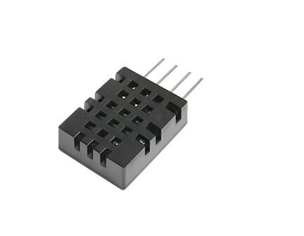
DHT20 SIP Packaged Temperature and Humidity Sensor
The DHT20 operates at 3.3V and communicates over I2C — a clean 3.3V-native sensor that pairs perfectly with ESP32 and 3.3V OLED displays with zero level shifting required.
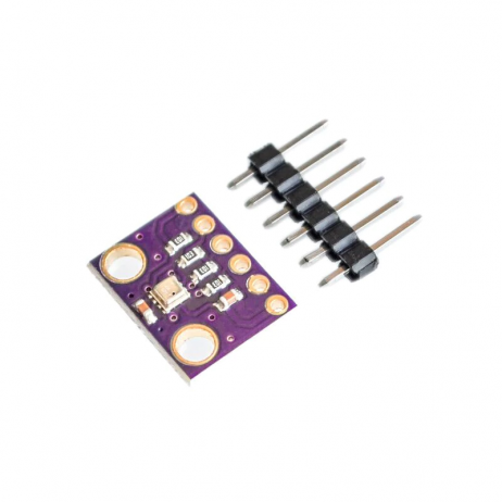
GY-BME280-3.3 Precision Altimeter Atmospheric Pressure Sensor Module
A 3.3V I2C sensor for temperature, humidity, and pressure. Ideal companion for 3.3V OLED display projects on ESP32 — all on the same voltage rail, no level shifters needed.
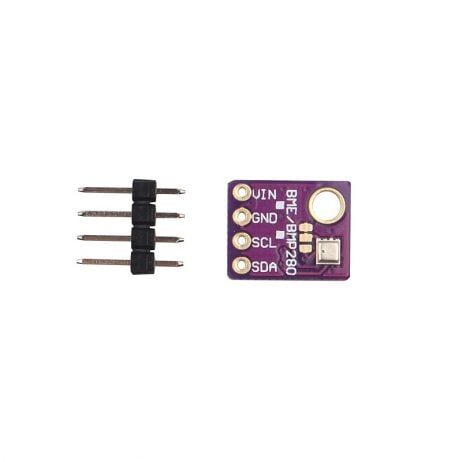
GY-BME280-5V Temperature and Humidity Sensor
The 5V version of the BME280 includes an onboard voltage regulator and level shifter — making it ideal for 5V Arduino projects with 5V-compatible OLED displays, all without extra components.
Recommended Sensors and Modules
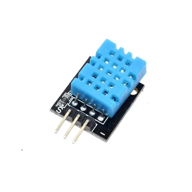
DHT11 Digital Relative Humidity and Temperature Sensor Module
Works at 3.3–5V. A popular choice for beginner sensor + display projects. Pair with any OLED at the matching voltage level for a simple weather display station.
Frequently Asked Questions
Will connecting a 3.3V OLED directly to Arduino Uno destroy it immediately?
Not always immediately, but over time the repeated exposure to 5V on 3.3V-rated inputs stresses the display driver IC. Some modules survive for months; others fail in minutes depending on the driver IC’s actual protection. It is not worth the risk — always level-shift or verify your module is 5V-tolerant before connecting.
Can I power a 3.3V OLED from Arduino’s 3.3V pin?
Yes for the VCC supply pin. The Arduino Uno/Nano 3.3V output can supply 50–150mA, which is enough for most small OLEDs (SSD1306 draws about 20mA at full brightness). However, if you are also running other 3.3V devices from the same pin, monitor total current draw to stay within limits.
Does a voltage divider work for SPI displays running at high speed?
Generally no. A resistor voltage divider combined with line capacitance creates an RC low-pass filter that limits signal rise times. At SPI speeds above 1–2 MHz, this causes signal distortion and communication errors. Use a proper level shifter (BSS138 or 74LVC245) for SPI connections.
I bought an OLED from a local market with no documentation. How do I know if it is 5V tolerant?
Look for an AMS1117-3.3 (or similar LDO) chip and small SMD resistors near the I2C pins on the PCB. If present, the module has onboard regulation and level shifting — it is likely 5V tolerant. If the OLED driver is the only significant chip, assume 3.3V only and use a level shifter to be safe.
Is Raspberry Pi more sensitive than ESP32 regarding input voltage?
Yes. Raspberry Pi GPIO pins have virtually no overvoltage protection and are extremely sensitive — even a brief 5V transient can permanently damage the SoC. Always assume 3.3V maximum input for all Raspberry Pi GPIO pins, with zero exceptions. Use proper level shifting for every 5V peripheral.
Shop Sensors and Display Modules at Zbotic
Find voltage-matched sensor and display module combinations at Zbotic.in — India’s trusted electronics store for makers, students, and engineers. Fast delivery across Mumbai, Pune, Delhi, Bengaluru, Hyderabad, and beyond.


Add comment