
When selecting a colour TFT display for your next project, one of the first decisions you face is the interface: TFT SPI vs parallel display comparison is a debate that Indian makers encounter regularly. Should you use a 4-pin SPI display or a much faster 8/16-bit parallel interface? The answer depends on your microcontroller, the resolution of your display, your available GPIO pins, and how fast you need to update the screen. This guide covers everything — bus bandwidth, practical speeds, wiring complexity, and real-world recommendations so you can make the right choice.
SPI vs Parallel: Interface Overview
TFT displays use two fundamentally different bus architectures to transfer pixel data from your microcontroller:
SPI (Serial Peripheral Interface)
SPI transfers data one bit at a time over a single MOSI (Master Out Slave In) data line, synchronised by a clock signal. A typical 4-wire SPI connection to a TFT uses only 4 pins: MOSI, SCK (clock), CS (chip select), and DC (data/command). Some displays also need a RST (reset) pin, making it 5 total.
The Raspberry Pi’s hardware SPI can reach up to 125 MHz on Pi 4, but most TFT controllers (ILI9341, ST7789, ST7735) support a maximum SPI clock of 40–80 MHz. Arduino Uno’s hardware SPI maxes out at 8 MHz (F_CPU/2), while ESP32 hardware SPI runs at up to 80 MHz.
Parallel Interface (8-bit / 16-bit)
Parallel interfaces send 8 or 16 bits simultaneously over dedicated data lines (D0–D7 or D0–D15), plus control signals WR (write strobe), RS (register select), CS, and RD. An 8-bit parallel connection requires at minimum 8 + 4 = 12 pins; 16-bit needs 16 + 4 = 20 pins.
Common parallel display controllers: ILI9341 (supports both SPI and 8/16-bit parallel), ILI9327, HX8357, ILI9486 (the large 3.5″ 480×320 displays common in India).
Speed Comparison and Bandwidth
This is where the decision gets technical. Let us look at achievable frame rates for a common 240×320 (76,800 pixels) display:
| Configuration | Effective Data Rate | Full Frame Update | Practical FPS |
|---|---|---|---|
| Arduino Uno SPI (8 MHz) | 1 MB/s | ~150 ms | ~6 FPS |
| ESP32 SPI (40 MHz) | 5 MB/s | ~30 ms | ~30 FPS |
| Raspberry Pi SPI (32 MHz) | 4 MB/s | ~38 ms | ~25 FPS |
| Arduino 8-bit Parallel (16 MHz) | ~8 MB/s | ~19 ms | ~50 FPS |
| STM32 16-bit Parallel (FSMC) | ~40 MB/s | ~4 ms | ~200+ FPS |
Key insight: On an Arduino Uno, 8-bit parallel is about 8x faster than SPI. However, on an ESP32 using DMA-driven SPI at 80 MHz, SPI performance rivals 8-bit parallel on a slower microcontroller. The MCU matters as much as the interface.
For pure raw speed, the winner is clear: 16-bit parallel with direct memory access (DMA) on STM32 or similar ARM MCUs can push 200+ FPS on a 320×240 display. But this requires dedicated hardware and more complex code.
Wiring Complexity and Pin Count
This is where SPI wins decisively for most hobbyist projects:
SPI Wiring (5 pins total):
Display VCC  → 3.3V
Display GND  → GND
Display CS   → D10
Display RESET → D9
Display DC   → D8
Display MOSI → D11
Display SCK  → D13
8-bit Parallel Wiring (12+ pins):
Display D0  → Arduino D22
Display D1  → Arduino D23
... (8 data lines)
Display D7  → Arduino D29
Display WR  → Arduino D30
Display RS  → Arduino D31
Display CS  → Arduino D32
Display RD  → Arduino D33
Display RST → Arduino D34
Plus VCC, GND, backlight...
An 8-bit parallel display eats almost all of Arduino Mega’s available digital pins. On an Arduino Uno (which only has 14 digital pins), running 8-bit parallel is barely possible and leaves almost nothing for other peripherals. SPI, by contrast, frees up GPIO for sensors, buttons, SD cards, and other peripherals.
Parallel displays often come soldered to a shield board for Arduino Mega or as a 40-pin FPC ribbon cable, making breadboard prototyping harder. SPI displays typically come with a standard 0.1″ pin header — breadboard-friendly out of the box.

LM35 Temperature Sensors
With SPI TFT taking only 5 pins, you have plenty of GPIO left for sensors like LM35 — add live temperature readouts to your display project easily.
Controller Compatibility
Not all microcontrollers handle both interfaces equally well:
Arduino Uno/Nano
- SPI: Hardware SPI at 8 MHz, easy to use. Recommended for Uno.
- Parallel: Software-emulated parallel only (bit-banged). Slow and leaves no free pins.
Arduino Mega 2560
- SPI: Hardware SPI at 8 MHz on standard pins.
- 8-bit Parallel: Works well — plenty of pins available. MCUFRIEND_kbv library makes it easy.
ESP32
- SPI: Excellent — hardware SPI at 40–80 MHz with DMA. Highly recommended.
- Parallel: I8080 parallel mode supported on newer ESP32-S3 and ESP32-P4 via the esp_lcd component.
STM32 (Blue Pill, Black Pill)
- SPI: Hardware SPI at up to 36 MHz. Good performance.
- 16-bit Parallel (FSMC): STM32F4xx has hardware FSMC controller — this is the fastest option available in hobbyist single-board form, enabling near-native LCD timing.
Raspberry Pi
- SPI: Hardware SPI at up to 125 MHz (though most displays cap at 40–64 MHz). Excellent for Pi.
- Parallel: Possible via GPIO bit-banging (very slow) or specialized hardware. Not practical for most projects.
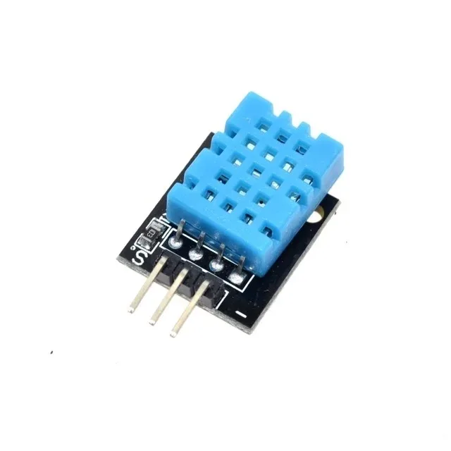
DHT11 Temperature and Humidity Sensor Module
Pair with an SPI TFT display for a compact weather station — SPI’s low pin count leaves room for digital sensors like DHT11 on your Arduino.
Library Support and Code Differences
Library support strongly favours SPI displays in the Arduino ecosystem:
SPI TFT Libraries
- Adafruit GFX + display-specific library (Adafruit ILI9341, Adafruit ST7789, etc.) — easiest to start with
- TFT_eSPI by Bodmer — fastest SPI library for ESP32/ESP8266, supports DMA, highly optimised
- LVGL — feature-rich GUI framework, works over SPI with TFT_eSPI backend
Parallel TFT Libraries
- MCUFRIEND_kbv — the go-to library for 8-bit parallel displays on Arduino Mega shields
- Adafruit TFTLCD — older, less maintained parallel library
- ESP-IDF esp_lcd component — for ESP32-S3 I8080 parallel interface, C-level code
Code portability is much better for SPI: the same Adafruit GFX or TFT_eSPI sketch runs on Arduino Uno, Mega, ESP32, and even Raspberry Pi with minor changes. Parallel display code is often hardware-specific and harder to port.
When to Use SPI vs Parallel
Choose SPI when:
- You are using Arduino Uno, Nano, or any pin-constrained MCU
- You need to share the bus with other SPI peripherals (SD card, sensors)
- You want simple, breadboard-friendly wiring
- Your update rate does not need to exceed ~30 FPS (static dashboards, menus, sensor readouts)
- You are using ESP32 or Raspberry Pi with fast hardware SPI
- Prototyping or learning — SPI is much easier to debug
Choose Parallel when:
- You need maximum frame rate for animations, video, or games
- You are using Arduino Mega or STM32 with many available GPIO pins
- Your display comes as an Arduino Mega shield (most 3.5″ and 4″ shields are parallel)
- You are building a dedicated graphics product where pin count is not a concern
- You are using ESP32-S3 or ESP32-P4 with hardware I8080 controller

BMP280 Barometric Pressure and Altitude Sensor I2C/SPI
I2C/SPI atmospheric sensor — use I2C mode alongside your SPI TFT display for a complete weather dashboard without pin conflicts.
Recommended Displays for Indian Projects
Based on the SPI vs parallel trade-offs, here are practical recommendations for common Indian maker scenarios:
- Arduino Uno beginners: 1.44″ or 1.8″ ST7735 SPI TFT (128×128 or 128×160) — affordable, simple wiring, good library support
- ESP32 projects: 2.4″ ILI9341 SPI (240×320) with TFT_eSPI — excellent performance, beautiful output
- Arduino Mega dashboards: 3.5″ ILI9486 parallel shield (480×320) — large display, no extra wiring needed if you use a shield
- Raspberry Pi: 3.5″ SPI display using fbcp-ili9341 driver — good performance for Pi desktop use
- High-performance graphics: STM32F4 Black Pill + 3.2″ ILI9341 parallel — game development level FPS

GY-BME280 Precision Atmospheric Pressure Sensor
Full temperature, humidity and pressure sensor in one — ideal for ESP32 + SPI TFT weather dashboard projects with plenty of GPIO to spare.
Frequently Asked Questions
Q1: Can I share the SPI bus between a TFT display and an SD card?
Yes — this is one of SPI’s greatest advantages. Use separate CS (chip select) lines for each device and toggle them appropriately. Many TFT display modules sold in India already include an SD card slot sharing the same SPI bus for this reason. Make sure your MISO line has pullup resistors if devices are connected but not actively selected.
Q2: Why does my SPI TFT show tearing artifacts?
Tearing happens when the display controller updates the screen while you are writing to it. Use the TE (tearing effect) pin if available, or implement double-buffering. With TFT_eSPI on ESP32, enabling DMA mode (#define USE_DMA_TO_TFT) significantly reduces tearing by allowing background transfers.
Q3: Is there any display that supports both SPI and parallel?
Yes — the ILI9341 controller supports 4-wire SPI, 3-wire SPI, and 8/16-bit parallel modes. The interface is selected via IM0-IM3 hardware pins on the module. Most pre-assembled modules have these pins soldered in a fixed configuration, so check the module’s documentation before assuming you can switch modes.
Q4: My 3.5″ parallel display shield shows garbage on Arduino Mega — how to fix?
Use the MCUFRIEND_kbv library and run its ID reader sketch first to identify your exact controller chip (ILI9486, ILI9481, or HX8357). Indian-market 3.5″ shields frequently use different controllers than labelled. Once you have the ID, the library’s constructor handles the rest automatically.
Q5: Does SPI work at 3.3 V and 5 V TFT displays?
Most modern TFT displays run at 3.3 V for logic. When driving from a 5 V Arduino, use a 74HC4050 level shifter or resistor divider (10 kΩ + 20 kΩ) on the SPI lines. Some display modules include onboard 3.3 V regulation and level shifting — check the product specification. Feeding 5 V logic into an unprotected 3.3 V display can damage it over time.
Make the Right Display Choice for Your Project
For most Indian hobbyist projects, SPI is the right choice — simpler wiring, great library support, and more than adequate speed for dashboards and menus. Parallel makes sense when you need maximum frame rate and have a pin-rich MCU like Arduino Mega or STM32.
Shop display modules, sensors, and all your project components at Zbotic.in — India’s maker-friendly electronics store with fast nationwide delivery.


Add comment