
Capacitor Marking Codes: How to Read SMD and Through-Hole Capacitors
If you’ve ever stared at a tiny capacitor trying to figure out its value, you’re not alone. Capacitor marking codes can seem cryptic at first — a three-digit number, a letter suffix, a colour band, or sometimes no marking at all. The good news is that once you know the system, reading any capacitor becomes quick and straightforward. This comprehensive guide covers every marking system used on through-hole and SMD (surface-mount) capacitors, with plenty of examples relevant to the component values Indian hobbyists and students encounter most often.
Why Capacitors Use Codes Instead of Full Values
Small capacitors simply don’t have enough surface area to print full values like “0.022µF” or “10000pF” clearly. So manufacturers use shorthand coding systems — the same way resistors use colour bands. The coding systems differ somewhat between capacitor types (ceramic disc, film, electrolytic, tantalum, SMD), so we’ll cover each one systematically.
Capacitance is measured in Farads (F), but practical capacitor values in electronics range from picofarads (pF, 10⁻¹² F) to thousands of microfarads (µF, 10⁻⁶ F). The unit conversions you’ll use constantly:
- 1 F = 1,000,000 µF
- 1 µF = 1,000 nF (nanofarads)
- 1 nF = 1,000 pF (picofarads)
- So: 1 µF = 1,000,000 pF = 1000 nF
Most ceramic capacitors are in the pF to nF range, most film capacitors span nF to low µF, and electrolytic capacitors cover µF to thousands of µF. Knowing approximately which range a capacitor physically looks like it should be helps avoid mistakes when decoding.
3-Digit Code System (Ceramic and Film Capacitors)
The 3-digit code is by far the most common system you’ll encounter on ceramic disc capacitors, multilayer ceramic capacitors (MLCCs), polyester film capacitors, and polypropylene capacitors. The system works exactly like the 3-band resistor colour code, but using digits instead of colours.
The Rule:
- First two digits = the significant figures of the value
- Third digit = the number of zeros to add (the multiplier as a power of 10)
- The result is always in picofarads (pF)
Exception: If the third digit is 8 or 9, special multipliers apply:
- 8 = multiply by 0.01
- 9 = multiply by 0.1
Common 3-Digit Codes Decoded:
| Marking | Calculation | Value in pF | Value in nF/µF |
|---|---|---|---|
| 100 | 10 × 10⁰ = 10 × 1 | 10 pF | 0.01 nF |
| 101 | 10 × 10¹ = 10 × 10 | 100 pF | 0.1 nF |
| 102 | 10 × 10² = 10 × 100 | 1,000 pF | 1 nF |
| 103 | 10 × 10³ = 10 × 1000 | 10,000 pF | 10 nF = 0.01 µF |
| 104 | 10 × 10⁴ = 10 × 10000 | 100,000 pF | 100 nF = 0.1 µF |
| 105 | 10 × 10⁵ | 1,000,000 pF | 1000 nF = 1 µF |
| 220 | 22 × 10⁰ = 22 × 1 | 22 pF | 0.022 nF |
| 221 | 22 × 10¹ = 22 × 10 | 220 pF | 0.22 nF |
| 222 | 22 × 10² = 22 × 100 | 2,200 pF | 2.2 nF |
| 223 | 22 × 10³ | 22,000 pF | 22 nF = 0.022 µF |
| 472 | 47 × 10² = 47 × 100 | 4,700 pF | 4.7 nF = 0.0047 µF |
| 473 | 47 × 10³ | 47,000 pF | 47 nF = 0.047 µF |
| 474 | 47 × 10⁴ | 470,000 pF | 470 nF = 0.47 µF |
The famous “104” capacitor:
Every Indian electronics student encounters “104” on a yellow ceramic disc capacitor. Using the formula: 10 × 10⁴ = 100,000 pF = 0.1 µF. This is by far the most common general-purpose bypass/decoupling capacitor value, used in virtually every mixed-signal circuit.

0.1µF Ceramic Capacitor (Pack of 50) — Code: 104
The most commonly used decoupling capacitor in electronics. Marked “104” on the body — 10 × 10⁴ = 100,000 pF = 0.1 µF. Pack of 50 for your component kit.
Electrolytic Capacitor Markings
Electrolytic capacitors (the cylindrical aluminium cans and the teardrop-shaped tantalum types) are large enough to print their values directly — no code needed. However, there are important markings you must understand:
Standard Electrolytic Markings:
The value and voltage are printed directly on the body: e.g., “100µF 25V” or “1000µF 16V”. The voltage rating is the maximum DC working voltage — never exceed this. Always leave at least 20–30% headroom (e.g., use a 25V-rated cap on a 15V rail).
Polarity Marking — Critically Important:
Electrolytic capacitors are polarised — they have a positive lead (anode) and a negative lead (cathode). Installing them backwards can cause the electrolyte to break down, producing heat, and potentially causing the capacitor to vent or even rupture explosively. Markings:
- The negative lead is marked with a white or light grey stripe running the full length of the capacitor body, usually with minus (−) symbols printed in the stripe.
- The positive lead is typically the longer lead on a new capacitor (though leads may have been trimmed in salvage components).
- The top of the capacitor has a K-shaped vent groove that ruptures safely if the capacitor is overstressed — never block this vent.
Reading the Date Code:
Electrolytic capacitors have a shelf life and operational life. Many manufacturers print a date code: typically a 4-digit code (e.g., “2342” = week 23 of year 2042, or year 2023 week 42 depending on convention). For critical applications, do not use electrolytic capacitors more than 3–5 years old without reforming them.
Temperature Rating:
Most consumer-grade electrolytics are rated at 85°C maximum. Premium grade (used in industrial and automotive) are rated at 105°C. In India’s hot climate, circuits in enclosed enclosures or near heat sources should always use 105°C-rated capacitors to ensure rated service life.
SMD Capacitor Marking Codes
SMD (Surface Mount Device) capacitors are increasingly common as Indian hobbyists and engineers work with modern PCB designs. Reading them is trickier because the components are tiny and markings are minimal — or completely absent.
Case 1: No Marking (Most Common for SMD Ceramic)
The vast majority of SMD MLCC (Multi-Layer Ceramic Capacitor) 0402, 0603, and 0805 packages have no visible marking at all. Values can only be determined by reading the original reel label or using an LCR meter. This is why organising SMD components carefully in labelled compartments is essential — once mixed, unmarked SMD caps of different values are impossible to distinguish visually.
Case 2: 3-Digit Code (Some SMD Ceramics)
Larger SMD ceramics (1206, 1210, and above) sometimes carry a 3-digit code identical to the through-hole system described above, in picofarads. E.g., “104” = 100nF = 0.1µF.
Case 3: SMD Electrolytic Markings
SMD aluminium electrolytic capacitors (the small cylindrical type) are marked with their capacitance and voltage rating directly, similar to through-hole electrolytics but in abbreviated form. E.g., “47/16” = 47µF at 16V. A dot or stripe on the body indicates the negative terminal.
Case 4: Tantalum SMD Capacitors
SMD tantalum capacitors (the small rectangular yellow, grey, or black components) use a capacitance code followed by a voltage code letter:
- The capacitance is in µF: e.g., “476” = 47 × 10⁶ pF = 47 µF (note: this is in µF, not pF like ceramic caps)
- Wait — actually for tantalum, many use µF directly: “47µ” or the EIA code: A=10V, B=16V, C=25V, D=35V, E=50V
- The positive terminal is marked with a stripe or a + symbol
- Warning: Tantalum caps are more sensitive to reverse polarity than aluminium — even a momentary reversal can cause permanent damage or fire
EIA Marking Codes (for SMD Film and Ceramic):
The EIA 3-character code system uses letters for the first two significant digits and a number for the multiplier, always in picofarads. This is less common but appears on precision film capacitors:
- Letters A–Z correspond to values: A=1.0, B=1.1, C=1.2, D=1.3, E=1.5, F=1.6, G=1.8, H=2.0, J=2.2 … and so on
- The third character is the multiplier (number of zeros after the two significant figures in pF)
- Example: “J54” = 2.2 × 10⁴ pF = 22,000 pF = 22 nF

0.1/100nF – TH-Multilayer Ceramic Capacitor (Pack of 50)
Through-hole multilayer ceramic caps marked “104”. A staple decoupling capacitor for microcontroller power supply pins, op-amps, and virtually every digital circuit.
Voltage and Tolerance Codes
After the capacitance value, you’ll often see letters indicating voltage rating and tolerance. These appear on ceramic disc capacitors, film capacitors, and some SMD types.
Tolerance Code (the letter after the 3-digit number):
| Letter Code | Tolerance | Typical Use |
|---|---|---|
| B | ±0.1 pF | Precision RF circuits |
| C | ±0.25 pF | Precision timing |
| D | ±0.5 pF | RF filters |
| F | ±1% | Precision timing/filters |
| G | ±2% | General precision |
| J | ±5% | Common general purpose |
| K | ±10% | Most ceramic caps (decoupling) |
| M | ±20% | General bypass caps |
| Z | +80% / -20% | Electrolytic caps |
So a ceramic capacitor marked “104K” is 0.1µF ±10%. “104M” is 0.1µF ±20%.
Voltage Rating Codes (separate from tolerance):
Voltage ratings on small ceramic disc capacitors are sometimes encoded as a letter or number prefix:
- Commonly, the voltage is just printed as a number: “50V”, “100V”, “250V”
- Some manufacturers use letter codes: e.g., A=10V, B=16V, C=25V, D=50V, E=100V (varies by manufacturer — check datasheet)
- On EIA standard SMD caps: a single letter prefix before the 3-digit code indicates voltage (1A = 10V, 1C = 16V, 1E = 25V, 1H = 50V, 2A = 100V)
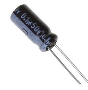
0.1µF 50V Capacitor (Pack of 50)
Rated at 50V DC — suitable for decoupling in 12V, 24V, and 48V circuits with comfortable headroom. Marked with value and voltage directly on the body for easy identification.
Colour Code (Vintage Capacitors)
Older capacitors — especially the tubular ceramic and mica capacitors common in equipment made before the 1980s — used colour band coding similar to resistors. You’ll encounter these in vintage radio repairs, which are increasingly popular among Indian hobbyists restoring AIR-era receivers.
The 5-band colour code for mica and ceramic capacitors:
- Band 1 (temperature coefficient): Black = C0G/NP0, White = N750, etc.
- Bands 2 and 3 (significant figures): Same as resistor colour code (Black=0, Brown=1, Red=2, Orange=3, Yellow=4, Green=5, Blue=6, Violet=7, Grey=8, White=9)
- Band 4 (multiplier): Same as resistor colour code — Black=×1, Brown=×10, Red=×100, Orange=×1000
- Band 5 (tolerance): Brown=±1%, Red=±2%, Green=±5%, White=±10%, Black=±20%
- All values are in picofarads
For example, a 5-band capacitor with bands: (White)–(Red)–(Green)–(Orange)–(Green) would decode as: temperature code N750 / 25 / ×1000 / ±5% = 25,000 pF = 25 nF ±5%.
Quick Reference Table: Most Common Capacitor Markings
| Marking | Value | Common Application |
|---|---|---|
| 10 (or 100) | 10 pF | Crystal load cap, RF tuning |
| 22 (or 220) | 22 pF | Crystal load cap, RF |
| 100 or 101 | 100 pF | RF bypass, timing |
| 102 | 1 nF (1000 pF) | RF filter, snubber |
| 103 | 10 nF (0.01 µF) | Filter, timing (555 timer) |
| 104 | 100 nF (0.1 µF) | Universal decoupling cap |
| 105 | 1 µF | Audio coupling, power filter |
| 473 | 47 nF (0.047 µF) | Audio crossover, timing |
| 474 | 470 nF (0.47 µF) | Power supply filter |
| 10µF 16V | 10 µF (electrolytic) | Audio coupling, PSU filter |
| 100µF 25V | 100 µF (electrolytic) | Power supply bulk decoupling |
| 1000µF 16V | 1000 µF (electrolytic) | PSU main filter cap |

9V Battery Operated LCR-T4 12864 LCD Graphical Transistor Tester
The best tool for identifying unknown capacitors. Place any capacitor in the test clips and the LCR-T4 instantly displays capacitance, ESR, and polarity — perfect when markings are worn or absent.
Frequently Asked Questions
Q1: A capacitor is marked just “104” — is it 104 pF or 0.1 µF?
It is 0.1 µF (= 100 nF = 100,000 pF). Using the 3-digit code: first two digits are “10”, third digit is “4” (meaning multiply by 10⁴ = 10,000). So 10 × 10,000 = 100,000 pF = 0.1 µF. The result of the 3-digit code is always in picofarads — then convert as needed. Never read the code as a direct picofarad value.
Q2: How do I identify an SMD capacitor with no markings?
For unmarked SMD ceramic capacitors, the only reliable methods are: (1) Use an LCR meter with SMD test clips — it will measure the capacitance directly. (2) Check the original component reel label or your PCB Bill of Materials for the expected value at that reference designator. (3) For critical repairs, unsolder the component and measure it. (4) Use a multimeter with capacitance mode — most modern digital multimeters can measure down to 1 nF, though accuracy at small pF values may be poor.
Q3: What does the voltage rating on a capacitor mean? Can I use a higher-rated cap instead?
The voltage rating is the maximum DC voltage the capacitor can handle safely. You can always substitute a capacitor with a higher voltage rating — e.g., a 100V-rated cap works fine in a 12V circuit. However, for electrolytic capacitors, using a much higher voltage rating than necessary can reduce effective capacitance in some types (especially Class II MLCCs which exhibit DC bias voltage effect). For electrolytics, stick within 2× the working voltage as a practical guideline for size and cost reasons.
Q4: Why do some capacitor values not exist — like 0.3 µF or 3 µF?
Capacitor values follow the same E-series standard as resistors (E6, E12, E24). Common series values are based on preferred numbers: 1.0, 1.2, 1.5, 1.8, 2.2, 2.7, 3.3, 3.9, 4.7, 5.6, 6.8, 8.2. This is why you see 0.33 µF, 3.3 µF, and 33 µF but not 0.3 µF, 3 µF, or 30 µF in the standard series. If you need an uncommon value, combine two capacitors in series or parallel.
Q5: Can I replace a capacitor with a different type (e.g., film instead of electrolytic)?
It depends on the application. Electrolytic capacitors are used for their large capacitance in small size (for power supply filtering, audio coupling), and they are polarised. Film capacitors are non-polarised, have lower ESR, and better high-frequency performance. For decoupling: a film or MLCC ceramic is always better than an electrolytic if the value is achievable (typically up to 10 µF in film, but getting expensive at high capacitance). Never substitute a non-polarised ceramic/film cap for an electrolytic in power supply rails without verifying the values match — the physical size difference reflects the much larger capacitance available in electrolytics.
Stock Up on Capacitors at Zbotic
From ceramic 104s to high-capacitance electrolytics, Zbotic carries a wide range of capacitors for Indian hobbyists, students, and engineers. All products shipped across India with fast delivery to 19,000+ pin codes.


Add comment