
TFT Display SD Card: Store & Display BMP Images on Arduino
Displaying colourful images on a TFT display with SD card support using Arduino is one of the most visually impressive projects a maker can build. Unlike monochrome GLCDs, a TFT (Thin Film Transistor) LCD can show thousands of colours at resolutions up to 320×240 pixels — enough to display photos, icons, splash screens, and UI elements. By storing BMP image files on a microSD card and loading them through the SD library, you effectively turn your Arduino into a simple picture viewer. In this tutorial, we cover everything from choosing the right TFT module, wiring it to Arduino, understanding the BMP file format, and writing efficient code to decode and display images.
Choosing the Right TFT Display Module
For Arduino-based BMP image display projects, two TFT modules are overwhelmingly popular in India:
- ILI9341 2.8″ TFT (320×240): The most common choice. Uses SPI interface, supports 16-bit colour (65,536 colours), and most importantly, includes an onboard microSD card slot. Available for around ₹300–400 at Indian electronics stores. Compatible with the Adafruit ILI9341 and MCUFRIEND_kbv libraries.
- ST7735 1.8″ TFT (160×128): Smaller and cheaper (₹150–200). Also has SD card slot. Good for compact projects where screen real estate is not critical.
Both modules communicate with Arduino via SPI, sharing the MOSI, MISO, and SCK lines with the SD card. They use separate chip select (CS) pins for display and SD card, so you can address them independently.
The key specification to check is whether the SD card slot uses a separate SPI CS pin from the display. On most popular modules, it does — meaning both the TFT and SD card share the 4-wire SPI bus, saving Arduino pins.
Understanding the BMP File Format
The BMP (Bitmap) format is used for TFT display projects because it stores raw, uncompressed pixel data — which makes it fast to decode on a microcontroller without complex decompression algorithms.
A BMP file has three sections:
- File Header (14 bytes): Contains the file signature (“BM”), file size, and offset to pixel data.
- DIB Header (40 bytes for BMP v3): Contains image width, height, colour depth, and compression type. For Arduino projects, use 24-bit (true colour) or 16-bit BMP only.
- Pixel Array: Raw RGB data, stored bottom-to-top by default. Each row is padded to a 4-byte boundary.
The Adafruit_ImageReader library handles all this decoding automatically. However, understanding the format helps when you encounter issues like upside-down images (typical BMP bottom-up storage) or colour-swapped pixels (BGR vs RGB byte order).
Image preparation tips:
- Convert your images to exactly the display’s resolution (e.g., 320×240 for ILI9341) using GIMP, Photoshop, or the free online tool Birme.
- Save as 24-bit BMP (not PNG or JPG — the Arduino SD library cannot decode these efficiently).
- Use a FAT32-formatted microSD card (up to 32GB supported).
- Keep filenames to 8.3 format (e.g., IMAGE1.BMP) for compatibility with the SD library’s FAT16/FAT32 parser.
Components Required
- Arduino Uno or Mega 2560
- 2.8″ ILI9341 TFT display module with onboard SD card slot
- microSD card (Class 10, 2–32GB, FAT32 formatted)
- Jumper wires
- USB cable
- PC for image preparation
- Optional: DHT11/DHT20 sensor for sensor dashboard overlay

DHT20 SIP Packaged Temperature and Humidity Sensor
Overlay live sensor readings on your TFT display BMP image background. The DHT20 provides accurate I2C readings for weather dashboards.
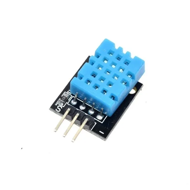
DHT11 Temperature & Humidity Sensor Module
Budget-friendly sensor to add real-time temperature and humidity data overlaid on your TFT image display project.
Wiring TFT and SD Card to Arduino
On a 2.8″ ILI9341 module, both the TFT display and SD card share the SPI bus. Here is the wiring for Arduino Uno:
| Module Pin | Function | Arduino Uno |
|---|---|---|
| VCC | Power | 5V |
| GND | Ground | GND |
| CS (TFT) | TFT Chip Select | Pin 10 |
| RESET | Display Reset | Pin 9 |
| DC/RS | Data/Command | Pin 8 |
| MOSI | SPI Data Out | Pin 11 |
| SCK | SPI Clock | Pin 13 |
| LED/BL | Backlight | 3.3V or 5V via 100Ω |
| MISO | SPI Data In (SD Card) | Pin 12 |
| SD_CS | SD Card Chip Select | Pin 4 |
Note: The ILI9341 module internally handles SPI voltage levels. On Arduino Mega, use pins 50 (MISO), 51 (MOSI), 52 (SCK) instead.
Installing Required Libraries
You need three libraries for this project:
- Adafruit_GFX — Core graphics primitives (lines, shapes, text). Install from Library Manager.
- Adafruit_ILI9341 — Hardware-specific driver for the ILI9341 TFT controller. Install from Library Manager.
- Adafruit_ImageReader — Reads BMP files from SD card and renders them to the display. Install from Library Manager.
- SD — Standard Arduino SD library (comes pre-installed with Arduino IDE).
In Arduino IDE 2.x, go to Tools → Manage Libraries, search for each name, and click Install. Accept dependency installation prompts.
Arduino Code to Display BMP from SD Card
Here is a complete, commented sketch that reads BMP images from an SD card and displays them on the ILI9341 TFT:
#include <SPI.h>
#include <SD.h>
#include <Adafruit_GFX.h>
#include <Adafruit_ILI9341.h>
#include <Adafruit_ImageReader.h>

#define TFT_CS   10
#define TFT_DC    8
#define TFT_RST   9
#define SD_CS     4

Adafruit_ILI9341    tft    = Adafruit_ILI9341(TFT_CS, TFT_DC, TFT_RST);
Adafruit_ImageReader reader;

void setup() {
  Serial.begin(9600);
  tft.begin();
  tft.setRotation(1); // Landscape mode
  tft.fillScreen(ILI9341_BLACK);

  if (!SD.begin(SD_CS)) {
    tft.setCursor(10, 10);
    tft.setTextColor(ILI9341_RED);
    tft.print("SD Card Error!");
    while (1);
  }

  // Display first BMP image
  ImageReturnCode stat = reader.drawBMP("/IMAGE1.BMP", tft, 0, 0);
  if (stat != IMAGE_SUCCESS) {
    tft.setCursor(10, 10);
    tft.setTextColor(ILI9341_YELLOW);
    tft.print("BMP load failed");
  }
}

void loop() {
  // Nothing in basic example
}
Auto Slideshow: Cycling Through Multiple BMP Images
#include <SPI.h>
#include <SD.h>
#include <Adafruit_GFX.h>
#include <Adafruit_ILI9341.h>
#include <Adafruit_ImageReader.h>

#define TFT_CS 10
#define TFT_DC  8
#define TFT_RST 9
#define SD_CS   4

Adafruit_ILI9341    tft    = Adafruit_ILI9341(TFT_CS, TFT_DC, TFT_RST);
Adafruit_ImageReader reader;

const char* images[] = {"/IMG1.BMP", "/IMG2.BMP", "/IMG3.BMP"};
const int numImages = 3;
int currentImage = 0;

void setup() {
  tft.begin();
  tft.setRotation(1);
  SD.begin(SD_CS);
}

void loop() {
  tft.fillScreen(0x0000);
  reader.drawBMP(images[currentImage], tft, 0, 0);
  currentImage = (currentImage + 1) % numImages;
  delay(3000); // Show each image for 3 seconds
}
Project Ideas: Image Slideshow and UI Panels
The TFT + SD card combination unlocks a wide range of practical and creative projects:
- Home Automation UI Panel: Store icon images on the SD card and display a touch-friendly UI. When a touch button is pressed (requires touch controller), load the appropriate icon and toggle a relay.
- Digital Photo Frame: Cycle through 10–50 photos stored on SD card. Add a light sensor (LDR) to auto-adjust display brightness based on ambient light.
- Industrial HMI Dashboard: Display machine status overlaid on a background image. Use serial data from a PLC to update on-screen values.
- Animated Splash Screen: Pre-load a sequence of BMP frames as an animation during device boot (similar to a loading animation).
- Plant Monitoring Display: Show a plant care icon from SD card alongside live moisture sensor readings for a smart garden dashboard.
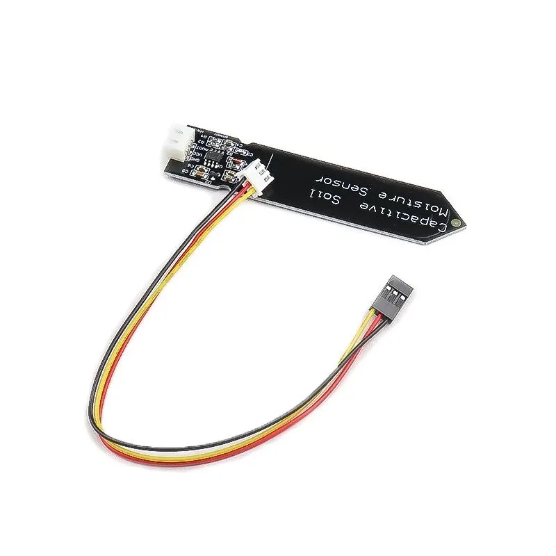
Capacitive Soil Moisture Sensor
Pair with your TFT display to build a smart plant monitor — display moisture levels and plant status icons from SD card on the TFT screen.

20A Range Current Sensor Module ACS712
Monitor current consumption and display bar graphs or icons on your TFT display. Great for energy monitoring dashboards.
Frequently Asked Questions
Why does my BMP image appear upside down on the TFT display?
BMP files store pixel rows from bottom to top by default. The Adafruit_ImageReader library handles this automatically and flips the image during rendering. If your image still appears inverted, check the tft.setRotation() value — try values 0, 1, 2, and 3 to find the correct orientation for your module.
Can I display JPG or PNG images instead of BMP?
The standard Adafruit libraries only support BMP natively on Arduino Uno/Mega due to RAM constraints. For JPEG support, the JPEGDecoder library works with larger boards (ESP32, Mega). PNG requires even more memory and is generally not recommended for 8-bit AVR Arduinos.
My SD card initialises but the BMP doesn’t load — what’s wrong?
First, confirm the filename is 8.3 format (max 8 characters + 3 extension, all uppercase is safest). Second, ensure the BMP is saved as 24-bit colour uncompressed. Third, check your SD_CS pin — it must match the pin connected to the SD card’s CS line, not the TFT’s CS line.
How long does it take to load a 320×240 BMP from SD card?
At SPI speeds achievable on Arduino Uno (4–8 MHz), a full 320×240 24-bit BMP (225 KB) loads in approximately 1–3 seconds. For faster loading, use an ESP32 or Arduino Due, which support higher SPI clock speeds and have more RAM for buffering.
Can I use a microSD module separately instead of the onboard SD card slot?
Yes. A standalone SPI microSD module works identically. Connect it to the same SPI bus as the TFT display, but assign it a different CS pin. The SD library initialisation call SD.begin(SD_CS) uses the pin you specify, so no other code changes are needed.
Start Building Your TFT Image Project Today
Combining a TFT display with an SD card gives your Arduino project a professional, full-colour display capability that was unthinkable on 8-bit microcontrollers just a decade ago. Whether you’re building a photo frame, an industrial HMI, or a sensor dashboard — this setup is affordable, capable, and well-supported by the Arduino ecosystem.
Browse display modules, sensors, and accessories at Zbotic.in — fast delivery across India, genuine components, and maker-friendly prices.


Add comment