
Pullup vs Pulldown Resistor: When and How to Use Each in Your Circuits
Understanding when and how to use pullup and pulldown resistors separates a confident circuit designer from a frustrated beginner. If you have ever seen a GPIO pin randomly trigger without being touched, or a button that misbehaves intermittently on your Arduino, a missing pullup or pulldown resistor is almost certainly the culprit. This guide explains the concept in full, shows you real wiring diagrams, and helps you choose the right resistor value every time.
The Floating Pin Problem
Every digital input pin on a microcontroller (Arduino, ESP32, STM32, etc.) needs to be in one of two states: HIGH or LOW. But what happens when nothing is connected to the pin and no switch has been pressed? The pin is said to be floating — it picks up stray electromagnetic fields from nearby wires, traces, and even your hand moving close to the board.
A floating pin reads random 1s and 0s, causing your code to behave unpredictably. The solution is elegantly simple: connect a resistor to either the supply voltage (VCC) or ground (GND) to give the pin a known default state. This is precisely what pullup and pulldown resistors do.
Think of it like a tug-of-war. Without a resistor, neither side is winning and the pin flaps in the breeze. The pullup or pulldown resistor is a weak anchor keeping the pin on the correct side until a switch or sensor actively pulls it the other way.
What Is a Pullup Resistor?
A pullup resistor connects between the signal line and the positive supply voltage (VCC or 3.3V/5V). When no switch is pressed or no active device is pulling the line low, the resistor ensures the pin reads HIGH (logic 1).
How it works:
- Switch open: Current flows from VCC through the resistor to the pin — Pin reads HIGH
- Switch closed (connects pin to GND): Current flows through the switch to GND — Pin reads LOW
This is called active low logic — pressing the button pulls the signal LOW rather than HIGH. It feels counterintuitive at first, but active low designs are extremely common in professional electronics because they are inherently more noise-immune (a broken wire looks like a HIGH, not a spurious trigger).
Typical circuit:
VCC (5V)
  |
 [10k Pullup Resistor]
  |
  +--------> GPIO Pin (reads HIGH by default)
  |
 [Switch]
  |
 GND
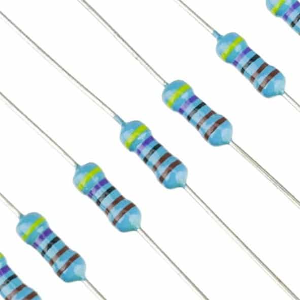
1/4W Metal Film Resistor (Pack of 100)
Precision metal film resistors with 1% tolerance — ideal for pullup and pulldown applications where accurate resistance matters for GPIO stability.
What Is a Pulldown Resistor?
A pulldown resistor connects between the signal line and ground (GND). When no switch is pressed or no active device is driving the line high, the resistor ensures the pin reads LOW (logic 0).
How it works:
- Switch open: Resistor connects pin to GND — Pin reads LOW
- Switch closed (connects pin to VCC): Current flows from VCC through the switch to pin — Pin reads HIGH
This is active high logic — pressing the button drives the signal HIGH. This feels more natural for beginners (button pressed equals logic 1) but is slightly more susceptible to noise pickup on long wires.
Typical circuit:
VCC (5V)
  |
[Switch]
  |
  +--------> GPIO Pin (reads LOW by default)
  |
 [10k Pulldown Resistor]
  |
 GND

0.25W Carbon Film Resistor (Pack of 100)
Affordable carbon film resistors in bulk packs — perfect to keep on your bench for quick pullup/pulldown resistor additions to breadboard prototypes.
Pullup vs Pulldown: When to Use Each
The choice between pullup and pulldown often comes down to three factors: convention, hardware constraints, and the logic level of the device you are interfacing.
| Scenario | Use Pullup | Use Pulldown |
|---|---|---|
| Simple pushbutton to GND | Yes – Standard approach | |
| Simple pushbutton to VCC | Yes – Standard approach | |
| I2C bus (SDA/SCL lines) | Yes – Always required | Never |
| Open-drain/open-collector output | Yes – Required | |
| Active-high sensors (DHT11, etc.) | Yes – Usually built-in | |
| MOSFET gate control | Yes – Keep gate LOW when idle | |
| Arduino internal pullup available | Yes – Use INPUT_PULLUP |
Choosing the Right Resistor Value
The resistor value is a balance between two competing concerns:
- Too low a resistance (e.g., 100 ohm): When the switch is closed and the line is forced to the opposite rail, a lot of current flows through the resistor to GND/VCC. This wastes power and can stress components. A 100 ohm pullup on a 5V line connected to GND when the button is pressed draws 50mA — wasted as heat.
- Too high a resistance (e.g., 1M ohm): The pin charges and discharges slowly, making it susceptible to capacitive coupling noise and causing slow rise/fall times that can confuse digital inputs.
The sweet spot for most GPIO applications is 4.7k to 10k ohms.
- 10k ohm — Most common value for simple button and switch applications. Very little quiescent current draw, good noise immunity.
- 4.7k ohm — Better for I2C buses at 400kHz (Fast Mode) where lower resistance ensures faster rise times
- 1k to 2.2k ohm — Used for I2C Fast Mode Plus (1MHz) or when driving LEDs via open-drain outputs
- 100k ohm — Used in ultra-low-power circuits where every microamp counts (IoT sensor nodes)
A quick power calculation: 10k pullup on 3.3V draws 0.33mA when the switch is pressed. On 5V that is 0.5mA. These are perfectly acceptable in almost all designs.
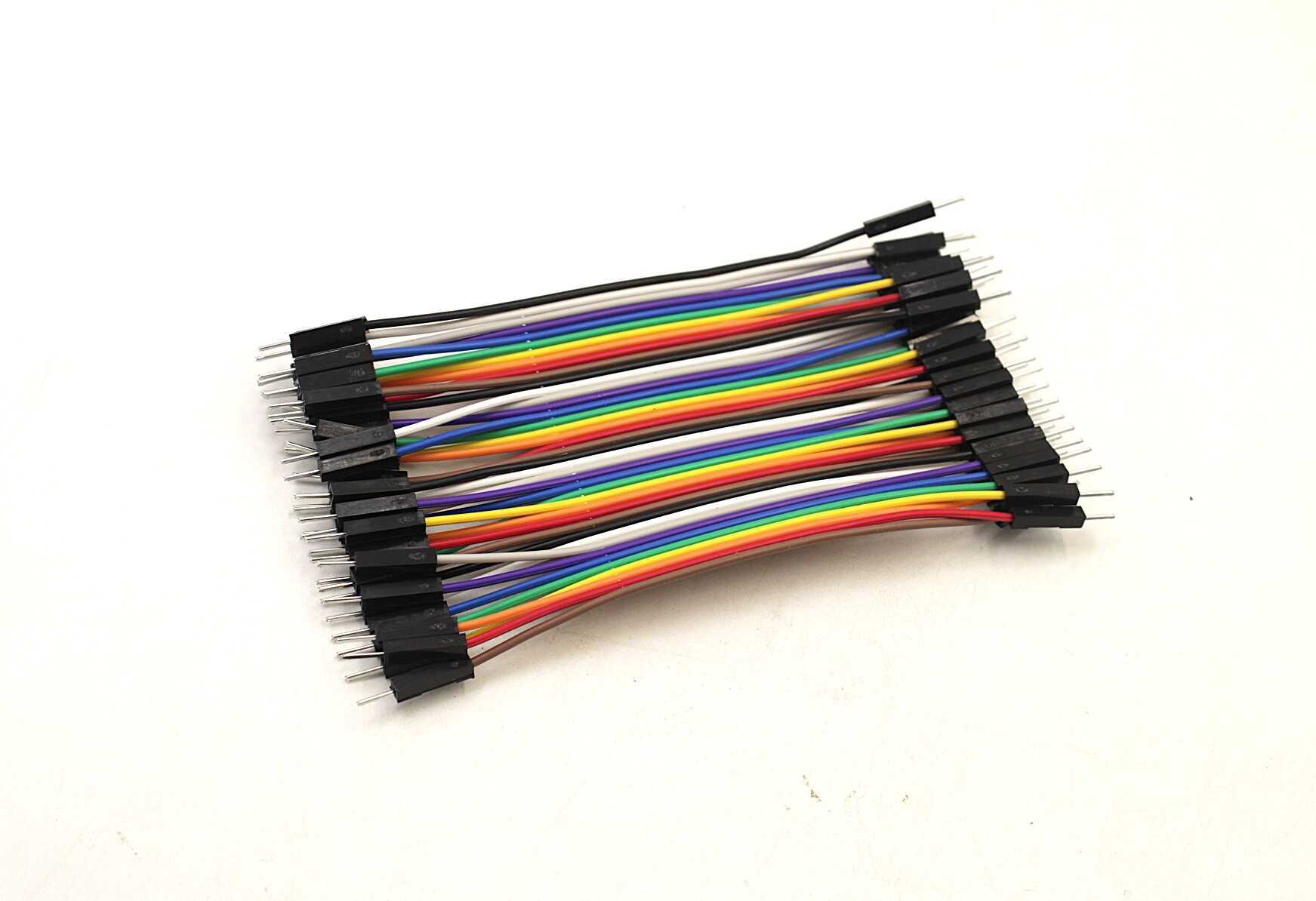
10CM Male To Male Breadboard Jumper Wires – 40Pcs
Quickly prototype your pullup and pulldown resistor circuits on a breadboard using these colour-coded jumper wires. 40-piece pack covers most project needs.
Arduino Internal Pullup Resistors
Arduino (and most other microcontrollers) has built-in pullup resistors on digital IO pins that you can enable in software — no external resistor needed. On Arduino Uno/Nano, the internal pullup is approximately 20k to 50k ohms.
To enable the internal pullup in Arduino code:
// Method 1 (modern, preferred)
pinMode(2, INPUT_PULLUP);

// Method 2 (older style)
pinMode(2, INPUT);
digitalWrite(2, HIGH); // enables internal pullup
With INPUT_PULLUP, a pressed button connected to GND reads as LOW (0) in your code. Remember to invert your logic:
if (digitalRead(2) == LOW) {
  // Button IS pressed (active low!)
}
Limitations of internal pullups: The 20k to 50k ohm internal resistance is too high for I2C buses and fast signals. For I2C, always use external 4.7k or 10k resistors. Internal pullups are fine for buttons and switches sampled at normal speeds.
I2C Bus and Pullup Resistors
I2C is an open-drain bus — devices can only pull the lines LOW. They rely on external pullup resistors to bring SDA and SCL back HIGH between communications. Without these pullups, the I2C bus simply does not work.
Most I2C modules sold in India (OLED displays, BME280, MPU6050, etc.) already have 4.7k or 10k pullup resistors on the module PCB itself. This is fine for a single device on short wires.
However, if you connect multiple I2C devices, their onboard pullups appear in parallel. Two 4.7k pullups in parallel equal 2.35k ohms. Six modules bring it to 783 ohms — now your pullup is too strong for reliable operation. Remove the onboard pullups from all but one module (desolder or cut the resistors) and use a single well-chosen external pullup instead.
I2C pullup recommendations:
- Standard mode (100kHz): 10k ohm works well for short runs under 50cm
- Fast mode (400kHz): 4.7k ohm for reliable data integrity
- Long wires or noisy environment: 2.2k to 4.7k ohm
- 3.3V systems: lean toward 4.7k ohm for adequate drive strength
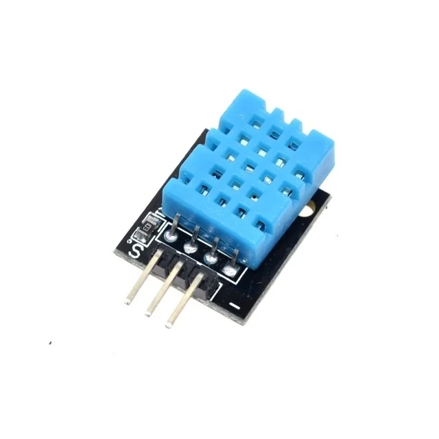
DHT11 Digital Humidity and Temperature Sensor Module
A classic sensor module that uses a single-wire protocol requiring a 4.7k to 10k pullup on the data pin. Perfect for practising pullup resistor wiring.
Frequently Asked Questions
Do I always need an external pullup or pulldown resistor?
Not always. Arduino and most microcontrollers have built-in pullup resistors (20k to 50k ohm) that you can enable via pinMode(pin, INPUT_PULLUP). For buttons and switches, the internal pullup is usually sufficient. For I2C buses and fast signals, you need external lower-value resistors (4.7k to 10k ohm).
Can I use the same resistor value for pullup and pulldown?
Yes. A 10k resistor works well in both pullup and pulldown configurations for most GPIO and button applications. The function is determined entirely by which rail the resistor is connected to (VCC for pullup, GND for pulldown), not the resistor value itself.
Why does my button input still bounce even with a pullup resistor?
Pullup and pulldown resistors fix the floating pin problem but do not fix mechanical switch bounce. When a mechanical switch closes, the contacts physically bounce 5 to 20 times in 5 to 20 milliseconds, generating multiple pulses. Fix this with a software debounce delay or a hardware RC debounce circuit using a 100nF capacitor in parallel with the switch.
What happens if I forget a pullup or pulldown resistor?
The pin is left floating and will randomly read HIGH or LOW based on electromagnetic interference. Your code will appear to trigger randomly, making the bug very hard to diagnose. A floating pin can also latch up sensitive CMOS inputs if exposed to static discharge — always define the idle state of every input pin.
Can two pullup resistors conflict with each other on the same line?
No conflict — they simply appear in parallel and the effective resistance is halved. But having too many pullups makes the line too stiff, preventing open-drain devices from pulling it low. On I2C buses with many modules, remove extra onboard pullup resistors and use a single appropriate value (4.7k to 10k) for the entire bus.
Stock Your Resistor Drawer at Zbotic
Never get caught without the right resistor value. Zbotic offers a wide selection of carbon film and metal film resistors in convenient bulk packs — perfect for Indian makers who prototype regularly. Browse resistors, breadboards, jumper wires, and more with fast delivery across India.


Add comment