


Description:
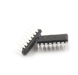
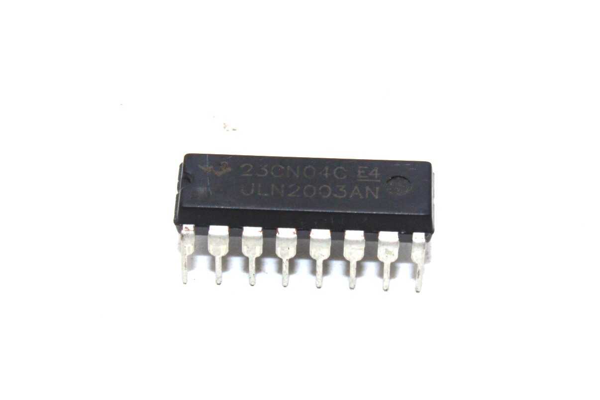
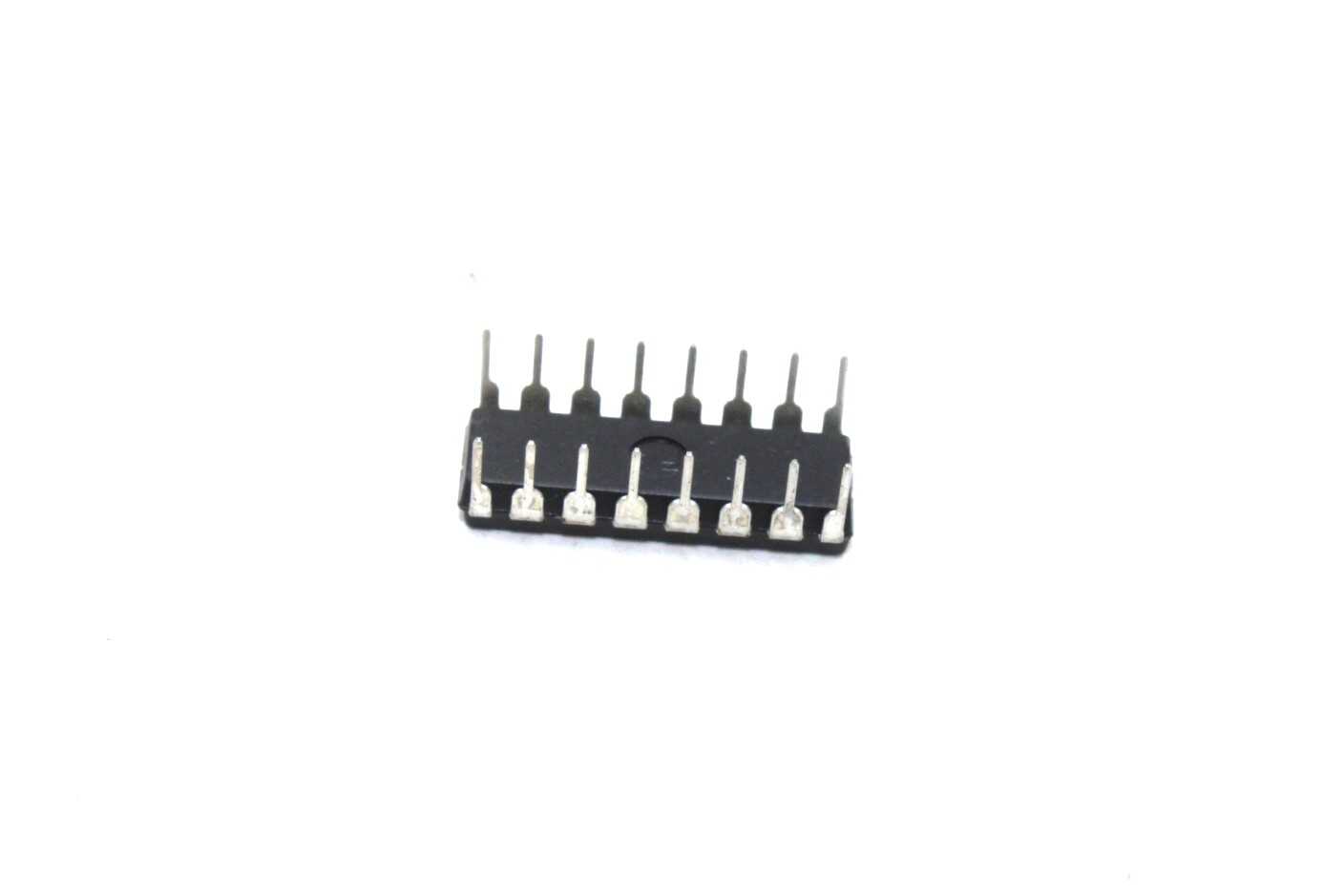
ULN2003 Motor Driver IC (DIP)
The ULN2003 is a 16-pin integrated circuit that contains seven Darlington pairs, each capable of driving loads up to 50V and 500mA. For each of these Darlington pairs, there are corresponding input and output pins, along with a ground pin and an optional common pin. The ground pin is connected to the system ground, while the common pin can be used if needed, though its use is optional.
Interestingly, the ULN2003 does not have a dedicated Vcc (power) pin. Instead, the power required for the internal transistors is drawn directly from the input pins. Below is a simple circuit diagram that can be used to test the operation of the ULN2003 IC.
Note: Product may vary from images shown in terms of brand name according to the availability.
Pin Diagram:
 4")
ULN2003 Pin Configuration:
| Pin Number | Pin Name | Description |
| 1 to 7 | Input 1 to Input 7 | Seven Input pins of Darlington pair, each pin is connected to the base of the transistor and can be triggered by using +5V |
| 8 | Ground | Ground Reference Voltage 0V |
| 9 | COM | Used as test pin or Voltage suppresser pin (optional to use) |
| 10 to 16 | Output 1 to Output 7 | Respective outputs of seven input pins. Each output pin will be connected to ground only when its respective input pin is high(+5V) |
Working of ULN2003 IC:
In the circuit consider the LED to be the loads and the logic pins (blue colour) as the pins connected to the Digital circuit or Microcontroller like Arduino. Notice that the Positive pin of the LED is connected to the positive load voltage and the negative pin is connected to the output pin of the IC. This is because when the input pin of the IC gets high the respective output pin will get connected to ground. So when the negative terminal of the LED is grounded it completes the circuit and thus glows. The loads connected to the output pin can be maximum of 50C and 500mA each. However you can run higher current loads buy combining two or more output pins to gather. For example if you combine three pins you can drive up to (3*500mA) ~1.5A.
The COM pin is connected to ground through a switch, this connection is optional. It can be used a test switch, meaning when this pin is grounded all the output pins will be grounded.
The ULN2803 is a Darlington array IC it can be used to drive Stepper and DC Motors, Relays, Solenoids, and other external circuits operating at high voltages and currents from simple CMOS logic signals from microcontrollers. It has 8 driving channels, each channel can withstand peak currents of 600mA. Suppression diodes are included for back EMF protection while driving inductive loads. The ULN2004 is used in the current version of our 8 Channel Relay Board to drive the onboard relays.
Features:
- Contains 7 high-voltage and high current Darlington pairs
- Each pair is rated for 50V and 500mA
- PDIP-16 package
- 500-mA-Rated Collector Current (Single Output)
- High-Voltage Outputs: 50 V
- Output Clamp Diodes
- Inputs Compatible With Various Types of logic
- Relay-Driver
Specification:
| IC Name | ULN2003 |
|---|---|
| Package/Case | DIP-16 |
Application:
- Used to drive high current loads using Digital Circuits
- Can be used to drive Stepper motors
- High current LED’s can be driven
- Relay Driver module (can drive 7 relays)
- Logic Buffers in digital electronics
- Used as Touch sensor for Arduino
Package Includes:
- 1 x ULN2003 Motor Driver IC (DIP)
Attachments:
Datasheet
( ⮝ click to download )
Technical Specifications
| Model | ULN2003 |
|---|---|
| SKU | AI0373 |
| Weight | 0.007 kg |
| Availability | Out of Stock |
Applications & Use Cases
The ULN2003 Motor Driver IC (DIP) is a versatile logic gate ics used across a wide range of applications including electronics projects, DIY builds, prototyping, and educational experiments.
Common use cases:
- Integrating into a custom electronics project
- Learning and experimenting with circuits
- Replacing or upgrading components in existing setups
This product is ideal for electronics enthusiasts, engineers, and students.
Technical Tip: Always verify voltage and current requirements before connecting to your circuit. Check datasheets for detailed specifications and pin configurations.
Shipping & Delivery
- Free shipping on orders above ₹999 across India
- Dispatched within 1-3 business days
- Expected delivery: 3-7 business days depending on location
- Secure packaging to ensure safe transit of electronic components


Ganesh S. (verified owner) –
good quality
Sunil Iyer (verified owner) –
Great ULN2003 Motor Driver IC. Mounting holes are accurate and the shaft fits perfectly with my coupling.
Sandeep Kumar (verified owner) –
Nice ULN2003 Motor Driver IC. Torque is decent. Mounting was easy. Good value for money.
Shreyas Saxena (verified owner) –
Pretty good ULN2003 Motor Driver IC. Using it in my conveyor project. Performs reliably.
Parth Ghosh (verified owner) –
Great ULN2003 Motor Driver IC. Mounting holes are accurate and the shaft fits perfectly with my coupling.
Yashwant Krishnan (verified owner) –
Great ULN2003 Motor Driver IC. Mounting holes are accurate and the shaft fits perfectly with my coupling.
Harsh Khanna (verified owner) –
Good ULN2003 Motor Driver IC. Runs well but generates a bit of heat under full load.
Sachin Mehta (verified owner) –
This ULN2003 Motor Driver IC runs very smoothly. Using it in my CNC project, very reliable.
Deepika Dubey (verified owner) –
This ULN2003 Motor Driver IC runs very smoothly. Using it in my CNC project, very reliable.
Vijay Thakur (verified owner) –
Good quality ULN2003 Motor Driver IC. Minor vibration at high speed but acceptable for my project.
Sahil Jain –
Outstanding quality ULN2003 Motor Driver IC. Been running for weeks continuously without any issues.
Anil Luthra (verified owner) –
Superb ULN2003 Motor Driver IC! Torque is exactly as specified. My project runs perfectly with this.
Aayush Kumar (verified owner) –
Good
Sameer Pandey (verified owner) –
Good quality ULN2003 Motor Driver IC. Minor vibration at high speed but acceptable for my project.
Vidya Mishra (verified owner) –
Love this ULN2003 Motor Driver IC. Silent operation and consistent speed. Worth every rupee.
Aditya Kulkarni (verified owner) –
Average ULN2003 Motor Driver IC. Works but the torque is slightly less than specified.
Aditya Dave (verified owner) –
Great quality ULN2003 Motor Driver IC. Shaft is precise and bearings are solid. No vibration at all.
Ananya Banerjee (verified owner) –
This ULN2003 Motor Driver IC is ideal for precision applications. Very happy with the purchase.
Tanvi Bajaj (verified owner) –
Good quality ULN2003 Motor Driver IC. Minor vibration at high speed but acceptable for my project.
Swati Hegde (verified owner) –
Love this ULN2003 Motor Driver IC. Silent operation and consistent speed. Worth every rupee.
Om Mehta (verified owner) –
Perfect ULN2003 Motor Driver IC for my automation project. Speed control works beautifully.
Arun Bose (verified owner) –
Great ULN2003 Motor Driver IC. Mounting holes are accurate and the shaft fits perfectly with my coupling.
Anushka Das –
Very satisfied with this ULN2003 Motor Driver IC. My robotic arm moves precisely with this motor.
Girish Bisht (verified owner) –
Average ULN2003 Motor Driver IC. Works but the torque is slightly less than specified.
Aman Shah (verified owner) –
Bought 4 of these for my robot. All working identically. Excellent consistency.