
Choosing the right resistor is one of the most fundamental skills in electronics. While most beginners focus on resistance value (in ohms), the wattage rating of a resistor is equally critical. A resistor with the correct resistance but insufficient wattage will overheat, burn out, or even cause a fire. This guide walks you through everything you need to know about resistor wattage ratings and power dissipation — from theory to practical selection.
What Is Power Dissipation in a Resistor?
Every resistor opposes the flow of electric current. As electrons push through this opposition, energy is released as heat. This is called power dissipation. The more current flows through a resistor, or the higher its resistance, the more heat is produced.
If the heat produced exceeds the resistor’s rated capacity, it starts to degrade. You may notice discoloration, a burning smell, or a complete open-circuit failure. In worst cases, it can damage surrounding components on the PCB.
Understanding power dissipation is essential for:
- LED current-limiting resistors
- Voltage divider networks
- Motor driver circuits
- Pull-up and pull-down resistors
- Load resistors in power supply testing
The Power Formula: P = I²R and P = V²/R
The fundamental relationship between power, voltage, current, and resistance comes from Ohm’s Law combined with the power equation:
P = V × I (Power = Voltage × Current)
Since V = I × R (Ohm’s Law), we can substitute to get two very useful forms:
- P = I² × R — Use this when you know the current and resistance
- P = V² / R — Use this when you know the voltage across the resistor and resistance
Let’s break down each formula with context:
Using P = I²R
If 50mA (0.05A) flows through a 100Ω resistor:
P = (0.05)² × 100 = 0.0025 × 100 = 0.25W
So you’d need at least a 0.25W resistor — and in practice, you should use a 0.5W or 1W resistor to allow thermal headroom.
Using P = V²/R
If 12V appears across a 470Ω resistor:
P = (12)² / 470 = 144 / 470 = 0.306W
Again, choose a 0.5W or 1W resistor in practice.
Standard Resistor Wattage Ratings
Resistors are manufactured in standard wattage sizes. Here are the most common ones you’ll encounter:
| Wattage Rating | Physical Size (approx.) | Typical Use Case |
|---|---|---|
| 1/8W (0.125W) | Very small, 1.5mm dia. | Low-power signal circuits, microcontroller GPIO |
| 1/4W (0.25W) | Standard, ~6mm body | Most general-purpose applications |
| 1/2W (0.5W) | Slightly larger, ~9mm body | LED drivers, moderate loads |
| 1W | Larger, ~11mm body | Power circuits, motor control |
| 2W | Noticeably larger | Chargers, power supplies |
| 5W, 10W, 25W | Large wirewound/ceramic | Dummy loads, high-power applications |
The most commonly stocked resistor in hobbyist kits is the 1/4W carbon film resistor, which handles the vast majority of Arduino, breadboard, and low-voltage prototyping needs.
How to Choose the Right Wattage Rating
Follow this simple three-step process:
- Calculate the actual power dissipation using P = I²R or P = V²/R
- Multiply by a safety factor of 2 (or at minimum 1.5) to get the required wattage
- Select the next standard wattage above your calculated requirement
For example, if your calculation gives 0.18W:
- Multiply by 2: 0.18 × 2 = 0.36W
- Next standard rating above 0.36W is 0.5W
- Use a 1/2W resistor
Temperature Considerations
Resistor wattage ratings are typically specified at 70°C ambient temperature. In hotter environments (like inside an enclosure), derate further. In Indian summer conditions where enclosure temperatures can exceed 50°C, it is wise to use a 3× safety factor rather than 2×.
Derating: The 50% Rule Explained
Professional engineers never run resistors at their full rated wattage. The industry standard is to derate to 50% of the rated power in normal operation. This dramatically extends component life, reduces thermal stress, and prevents failures.
The 50% derating rule means:
- A 0.25W resistor should only handle 0.125W in real designs
- A 0.5W resistor should handle max 0.25W
- A 1W resistor should handle max 0.5W
This is why many engineers automatically “double up” — if their calculation shows 0.25W needed, they use a 0.5W resistor. It’s good engineering practice and costs almost nothing extra.
Pulse vs Continuous Power
If a resistor only carries current in short pulses (like a buzzer drive or motor brake), it can handle higher peak power than its rated continuous power — sometimes 5-10× for very short pulses. However, always calculate the average power for continuous rating comparisons.
SMD vs Through-Hole Power Resistors
Surface-mount (SMD) resistors follow a similar wattage rating system, with sizes standardized by package code:
| SMD Package | Size (mm) | Typical Max Wattage |
|---|---|---|
| 0402 | 1.0 × 0.5 | 0.063W (1/16W) |
| 0603 | 1.6 × 0.8 | 0.1W (1/10W) |
| 0805 | 2.0 × 1.25 | 0.125W (1/8W) |
| 1206 | 3.2 × 1.6 | 0.25W (1/4W) |
| 2010 | 5.0 × 2.5 | 0.75W |
| 2512 | 6.35 × 3.2 | 1W |
Through-hole resistors are better suited for high-power applications because they can dissipate heat more effectively, especially when mounted with some air gap above the PCB. For prototyping on breadboards, through-hole 1/4W resistors are the go-to choice.
Practical Calculation Examples
Example 1: LED Current-Limiting Resistor
Supply: 5V, LED forward voltage: 2V, LED current: 20mA
Resistor value: (5 – 2) / 0.02 = 150Ω
Power: I²R = (0.02)² × 150 = 0.0004 × 150 = 0.06W
Result: A standard 1/4W (0.25W) resistor is more than adequate — it runs at just 24% of rating.
Example 2: 12V Relay Coil Drive via Transistor
Relay coil resistance: 360Ω, supply: 12V
Current: 12V / 360Ω = 33.3mA
Power: (0.0333)² × 360 = 0.001109 × 360 = 0.399W
Result: Choose a 1W resistor if you add a current-limiting resistor in series, or ensure the transistor’s base drive resistor dissipates within its rating.
Example 3: Voltage Divider for 3.3V from 5V
R1 = 1.8kΩ, R2 = 3.3kΩ, supply: 5V
Total current: 5V / (1800 + 3300) = 5 / 5100 = 0.98mA
Power in R1: (0.00098)² × 1800 = 0.00172W
Power in R2: (0.00098)² × 3300 = 0.00316W
Result: Even tiny 1/8W resistors are completely fine here. Use 1/4W for extra margin.
Common Mistakes to Avoid
- Using 1/4W resistors everywhere blindly — Always calculate first. For high-voltage or high-current circuits, this will fail.
- Ignoring ambient temperature — Inside enclosures in Indian summers, actual wattage capacity drops significantly.
- Forgetting series resistors with LEDs — Connecting LEDs directly to power with no resistor is the most common beginner mistake. Always use a current-limiting resistor.
- Not accounting for worst-case voltage — Power supplies may output higher voltage under no-load conditions. Use the maximum expected voltage in calculations.
- Mixing up R and Ω symbols — On resistors, 1K = 1000Ω, 4R7 = 4.7Ω, 100R = 100Ω. When in doubt, check the color code.
Recommended Products from Zbotic

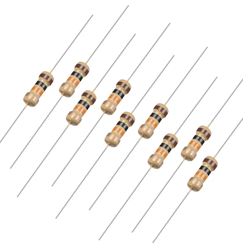
0 Ohm 0.25W Carbon Film Resistor (Pack of 100)
The classic 1/4W carbon film resistor — ideal for breadboard prototyping and general-purpose circuits. Comes in a convenient pack of 100.
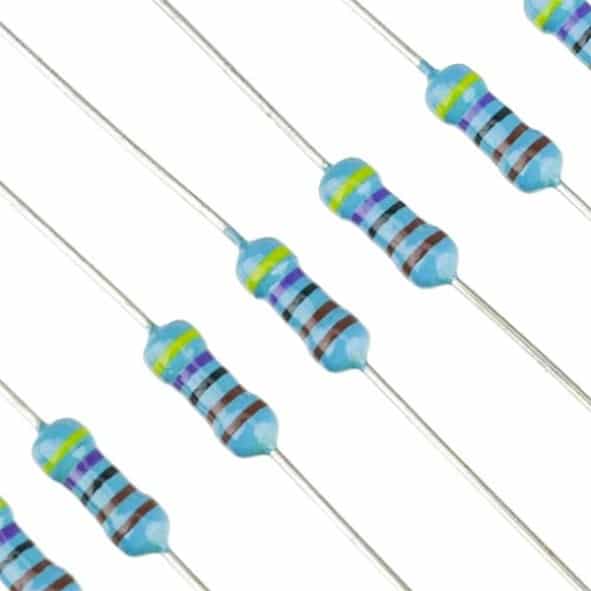
1.5 Ohm 0.25W 1/4W Metal Film Resistor MFR (Pack of 100)
Metal film resistors offer tighter tolerance (1%) and lower noise than carbon film — essential when precision power dissipation matters.
10 Ohm 0.25W Carbon Film Resistor (Pack of 50)
A must-have value for motor snubber circuits, LED current limiting, and voltage divider experiments. Pack of 50 ensures you never run short.

LCR-T4 LCD Graphical Transistor Tester & Component Meter
Instantly measure resistance, capacitance, and more. Ideal for verifying resistor values and wattage-related component health in your projects.
Frequently Asked Questions
Q: Can I use a higher wattage resistor than required?
A: Absolutely. Using a higher wattage resistor than needed is always safe. A 1W resistor will work perfectly fine where a 0.25W is the minimum requirement. It will simply run cooler. The resistance value must match, but wattage can always go higher.
Q: What happens if I use a lower wattage resistor?
A: The resistor will overheat. Initially it may drift in resistance value, causing unpredictable circuit behaviour. Eventually the resistive element burns open (infinite resistance), breaking the circuit. In rare cases with very high power, it may smoke or catch fire.
Q: How do I identify a resistor’s wattage by looking at it?
A: For through-hole resistors, physical size is the key indicator. A 1/4W resistor has a body about 6mm long and 2mm in diameter. A 1/2W is slightly larger (9mm body), and a 1W is noticeably bigger still. SMD resistors use package codes (0402, 0603, 0805, etc.) which directly correspond to wattage as listed in the table above.
Q: Do resistors have polarity?
A: No, standard resistors (carbon film, metal film, wire wound) are non-polar and can be inserted in either direction. Only certain special components like varistors and thermistors need careful handling, and even those are typically non-polar.
Q: What is the difference between carbon film and metal film resistors in terms of wattage?
A: Both types are available in the same standard wattage ratings. However, metal film resistors have tighter tolerance (typically 1% vs 5% for carbon film) and lower temperature coefficient, meaning their resistance value drifts less with heat. For power-critical or precision circuits, metal film is preferred even if both are rated at the same wattage.
Q: Is it safe to use a 0.25W resistor with a 3.3V Arduino GPIO pin?
A: Yes. Arduino GPIO pins source/sink a maximum of 40mA. At 3.3V with even a 10Ω resistor, P = (0.04)² × 10 = 0.016W, well within the 0.25W rating. For typical pull-up/pull-down resistors (10kΩ), the power is negligible.


Add comment