
Choosing the right motor speed sensor can make or break a robotics or automation project. Whether you’re building a precision CNC machine, a self-balancing robot, or an industrial conveyor controller, the encoder you pick determines how accurately the system tracks motion. In the Indian maker community, two types dominate: optical encoders and magnetic encoders. Both convert rotational movement into electrical pulses, but they do it very differently — and each has environments where it shines or struggles.
This guide breaks down every important difference between optical and magnetic encoders, explains the physics behind each technology, and gives you a practical framework to decide which one belongs in your next project.
How Motor Speed Sensors Work
A rotary encoder (the most common motor speed sensor in hobby and semi-industrial applications) is a transducer that converts mechanical rotation into digital pulses. The microcontroller or motor driver counts these pulses over time to derive:
- Speed (RPM) — pulses per second divided by pulses per revolution
- Position — cumulative pulse count (for absolute or incremental tracking)
- Direction — using two channels (A and B) in quadrature
Both optical and magnetic encoders use the same principle of interrupting or modulating a signal at regular angular intervals. The difference is what generates those intervals: a patterned disk blocking light, or a magnetised wheel altering a magnetic field.
Optical Encoders Explained
An optical encoder uses a code disk — typically a thin glass or plastic disc — printed or etched with alternating opaque and transparent segments. An infrared LED shines light through the disc; a photodetector on the other side sees light only when a transparent slot passes by. Each light pulse is one count.
Types of Optical Encoders
- Transmissive (through-beam): LED and detector face each other with the disc between them. Common in hobby motors (like the 25GA-370 gear motor with encoder). High resolution, simple circuit.
- Reflective: LED and detector sit on the same side; the disc has reflective and non-reflective zones. Compact but slightly less noise-immune.
- Absolute optical encoders: Multiple tracks on the disc encode position as a binary or Gray code word — no homing needed at power-up.
Advantages of Optical Encoders
- Very high resolution: Commercial optical encoders easily reach 1000–10,000 PPR (pulses per revolution). Hobby versions on gear motors are typically 11–20 PPR on the motor shaft, multiplying to hundreds of counts per output shaft revolution after the gearbox.
- No magnetic interference: Ideal near strong electromagnets, speakers, or other motors.
- Sharp, clean pulses: The optical transition is fast, giving crisp digital edges that are easy to count at high speed.
- Well-understood technology: Decades of literature, libraries, and application notes available.
Disadvantages of Optical Encoders
- Sensitive to contamination: Dust, oil, moisture, or metal shavings on the code disc degrade or kill the signal. Bad for outdoor or industrial environments.
- Fragile disc: The code disc can crack or shatter under vibration if it is glass, or warp under heat if it is plastic.
- Alignment critical: The LED, disc, and detector must be precisely aligned; vibration can shift them.
- LED aging: The infrared LED dims over years of operation, eventually causing missed counts.
Magnetic Encoders Explained
A magnetic encoder replaces the optical disc with a magnetised ring or multipole magnet attached to the motor shaft. A Hall-effect sensor or magnetoresistive (MR) sensor fixed to the housing detects the alternating north-south poles as the shaft spins. Each pole transition is one count.
Types of Magnetic Encoders
- Hall-effect encoders: Use discrete Hall sensors. Robust, inexpensive, suitable for moderate resolutions (up to ~2000 PPR in modern ICs). Most brushless motors (BLDC) use three Hall sensors for commutation — this doubles as a coarse speed sensor.
- Magnetoresistive (AMR/GMR) encoders: Use thin-film resistors whose resistance changes with magnetic field orientation. Higher resolution (up to 65536 PPR), excellent for servo drives and robotics joints.
- Absolute magnetic encoders: ICs like the AS5048A give 14-bit absolute position over SPI/I²C — no homing needed, single-chip solution.
Advantages of Magnetic Encoders
- Highly resistant to contamination: No optical path to block. Works in dusty, wet, oily, or smoky environments.
- Robust to vibration and shock: No fragile glass disc; the magnet ring is durable.
- Compact modern ICs: A single IC (e.g., AS5600) on the PCB plus a diametrically magnetised disc magnet on the shaft provides contactless absolute angle sensing in under 10mm of axial space.
- Works at temperature extremes: Typically rated −40°C to +125°C vs. optical’s narrower range.
Disadvantages of Magnetic Encoders
- Susceptible to stray magnetic fields: Strong external magnets (from adjacent motors, solenoids, or speakers) can corrupt the reading.
- Resolution limitations on low-cost versions: Budget Hall-effect encoders on cheap gear motors may only give 11–20 PPR before the gearbox.
- Signal conditioning: The sinusoidal output of MR sensors needs interpolation electronics to achieve full resolution — adds cost.
- Magnet placement critical: The disc magnet must be centred on the shaft axis to within 0.5mm for best accuracy.
Side-by-Side Comparison
| Feature | Optical Encoder | Magnetic Encoder |
|---|---|---|
| Operating principle | Light through/reflected by code disc | Hall / MR sensor detects magnet poles |
| Typical resolution (hobby) | 11–500 PPR | 11–4096 PPR (IC-based) |
| Dust / oil resistance | Poor — disc can be blocked | Excellent |
| EMI / magnetic immunity | Excellent | Poor near strong magnets |
| Vibration tolerance | Moderate (disc can crack) | Excellent |
| Cost (hobby grade) | ₹150–₹600 integrated with motor | ₹100–₹500 (IC + magnet) |
| Absolute position | Available (multi-track) | Available (AS5048, AS5600) |
| Ideal environment | Clean, indoor, low vibration | Outdoor, dusty, high vibration |
Resolution and Accuracy Deep Dive
When people say “resolution” they usually mean PPR (pulses per revolution) — but the effective angular resolution depends on whether you use single-ended counting or quadrature decoding:
- Single channel (1× counting): angular step = 360° / PPR
- Quadrature (4× counting, both edges of A and B): angular step = 360° / (4 × PPR)
So a 20 PPR encoder gives 80 counts per revolution in quadrature mode — that’s 4.5° per count. For a gear motor with a 1:34 gearbox (like the 25GA-370 at 12 RPM), the output shaft has 80 × 34 = 2720 counts/revolution — sufficient for position control of a robot arm joint.
For CNC or delta-robot applications needing sub-millimetre positioning, 1000+ PPR on the motor shaft is preferred. At that level, only premium optical encoders or high-resolution magnetic ICs (AS5048A, 14-bit = 16384 steps/rev) deliver the required granularity.
Environmental Durability
India’s climate adds a layer of complexity. Coastal workshops near Mumbai or Chennai face salt-laden humid air; factories in UP or Rajasthan deal with fine particulate dust; outdoor agricultural robots encounter mud and water. Here’s how each encoder type fares:
- High humidity (>80% RH): Optical discs can fog; photodetectors accumulate condensation. Magnetic encoders with conformal-coated PCBs are far more reliable.
- Fine dust: Even IP-rated optical encoders need careful sealing. Magnetic sensors with no optical path survive easily.
- Vibration (motors on uneven terrain): Magnetic encoders win again — no fragile disc.
- High temperature (>60°C ambient): Both degrade, but magnetic Hall sensors typically have wider industrial temperature specs.
- Near large motors or welding equipment: Optical encoders are immune to magnetic interference; magnetic encoders need shielding.
Cost Considerations in India
For Indian hobbyists and startups, budget is a real constraint. Here’s the realistic cost picture:
- Integrated gear motor with optical encoder (e.g., 25GA-370 with encoder): ₹450–₹700 — includes motor + encoder. Best value for closed-loop robot drive wheels.
- Standalone optical encoder module (LM393 slot sensor + disc): ₹40–₹120. Low resolution (1–20 PPR) but dirt cheap for basic speed sensing.
- AS5600 magnetic encoder IC + magnet: ₹80–₹200 for the IC, ₹30–₹80 for the magnet — total under ₹300 for absolute angle sensing up to 12-bit (4096 steps). Extremely popular in brushless gimbal and drone motor control.
- AS5048A (14-bit, SPI): ₹400–₹700 — used in high-end servo joints and robotics.
Which Encoder Should You Choose?
Use this decision tree:
- Outdoor / dusty / wet environment? → Magnetic encoder every time.
- Near strong electromagnetic sources (welders, large motors)? → Optical encoder to avoid EMI corruption.
- Need absolute position (no homing at startup)? → AS5600 or AS5048A magnetic IC, or multi-track optical. Both work well.
- Budget under ₹200 for speed sensing only? → LM393 slot sensor + slotted disc (optical, incremental). Simple Arduino interrupt-based counting.
- Brushless gimbal motor commutation + speed sensing? → Magnetic IC (AS5600) is the standard choice — it sits on the stator PCB and reads a magnet on the shaft without contact.
- CNC or high-resolution positioning (>1000 PPR on motor shaft)? → High-quality optical encoder or AS5048A magnetic IC.
Wiring an Encoder to Arduino
For a standard 2-channel incremental encoder (optical or Hall magnetic):
// Encoder on pins 2 (A) and 3 (B) — hardware interrupt pins on Uno
volatile long encoderCount = 0;

void setup() {
  pinMode(2, INPUT_PULLUP);
  pinMode(3, INPUT_PULLUP);
  attachInterrupt(digitalPinToInterrupt(2), encoderISR, CHANGE);
  attachInterrupt(digitalPinToInterrupt(3), encoderISR, CHANGE);
  Serial.begin(115200);
}

void encoderISR() {
  int a = digitalRead(2);
  int b = digitalRead(3);
  if (a == b) encoderCount++;
  else encoderCount--;
}

void loop() {
  static long lastTime = 0;
  static long lastCount = 0;
  if (millis() - lastTime >= 500) {
    long delta = encoderCount - lastCount;
    // RPM = (delta / PPR) * (60000 / 500) — adjust PPR for your encoder
    Serial.print("Counts: "); Serial.println(encoderCount);
    lastCount = encoderCount;
    lastTime = millis();
  }
}
For an AS5600 magnetic encoder (I²C absolute angle):
#include <Wire.h>
#define AS5600_ADDR 0x36

void setup() { Wire.begin(); Serial.begin(115200); }

void loop() {
  Wire.beginTransmission(AS5600_ADDR);
  Wire.write(0x0E); // RAW ANGLE register (high byte)
  Wire.endTransmission(false);
  Wire.requestFrom(AS5600_ADDR, 2);
  int angle = (Wire.read() << 8) | Wire.read();
  float degrees = angle * 360.0 / 4096.0;
  Serial.println(degrees);
  delay(10);
}
Recommended Products from Zbotic
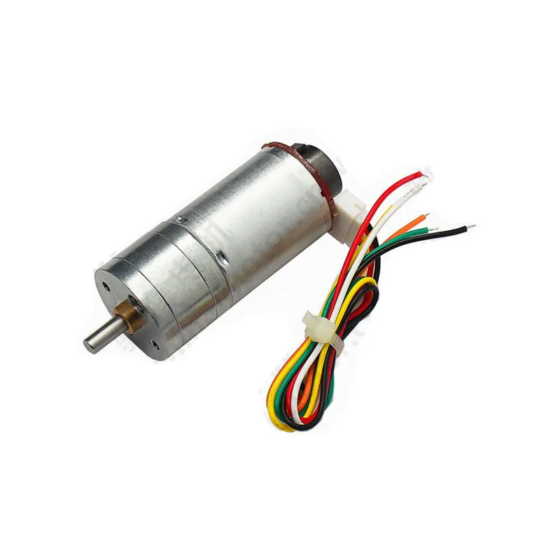
25GA-370 12V 12RPM DC Reducer Gear Motor with Encoder
Integrated optical encoder on a robust 12V geared DC motor — perfect for closed-loop robot drive wheels and conveyor feedback control.
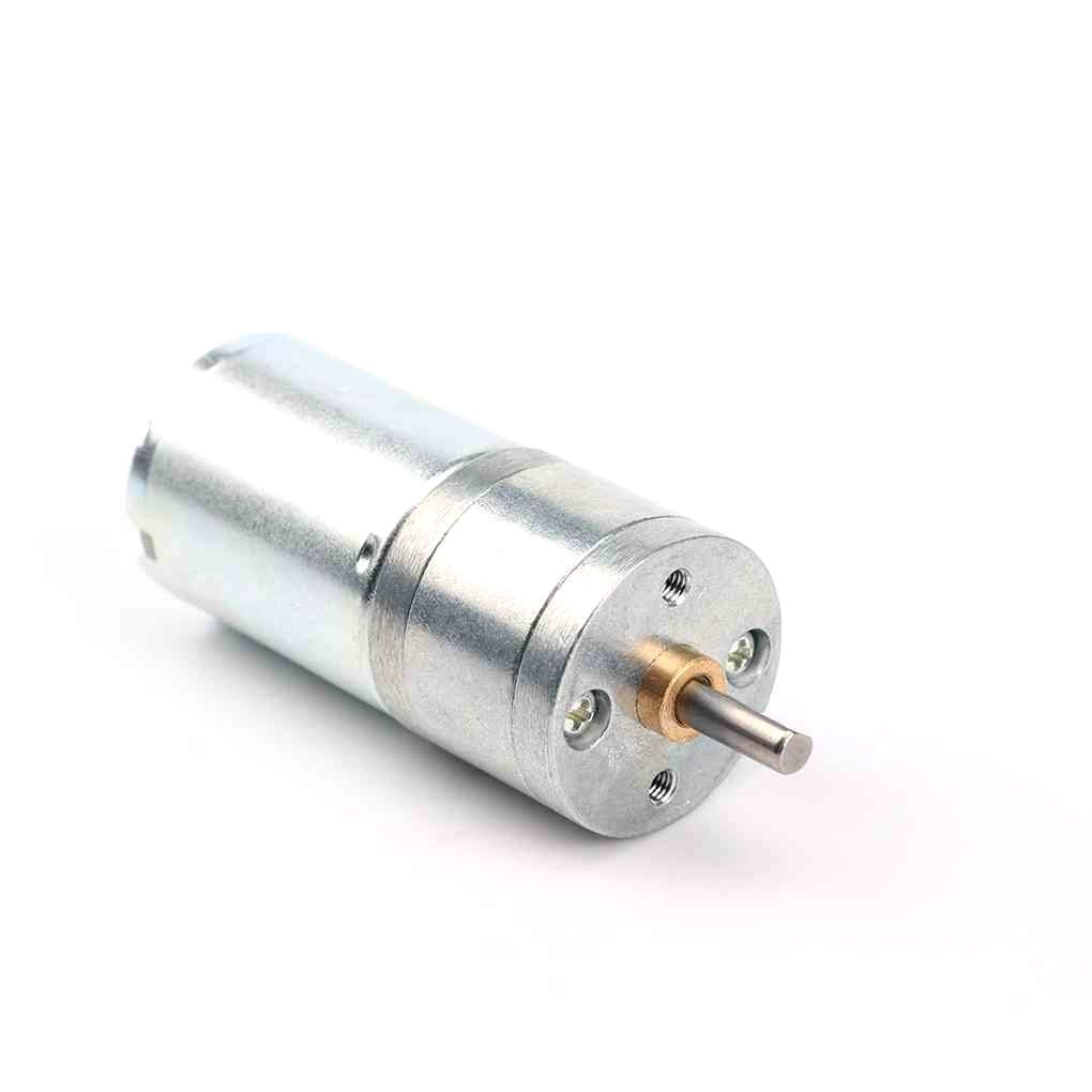
25GA-370 12V 12RPM DC Reducer Gear Motor
Same reliable gear motor without encoder — add your own AS5600 magnetic encoder IC for a fully customisable closed-loop setup.
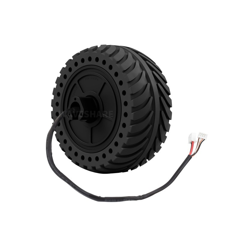
Waveshare DDSM115 Direct Drive Servo Motor
Hub motor with built-in magnetic encoder and closed-loop driver — no separate encoder needed, ideal for UGV and mobile robot wheels.
FAQ
Can I use a hall-effect encoder as a motor speed sensor for Arduino?
Yes. The Hall sensor output is a digital square wave that can be read on any Arduino digital pin using attachInterrupt(). Count pulses over a fixed time window and divide by PPR to get RPM.
What is PPR vs CPR in an encoder?
PPR (Pulses Per Revolution) is the number of rising edges on one channel per shaft revolution. CPR (Counts Per Revolution) usually means 4× PPR when quadrature decoding counts both edges on both channels. Always clarify which the manufacturer specifies.
My optical encoder gives wrong readings near a brushed DC motor — why?
Brushed motors generate significant EMI that can false-trigger LM393-based optical sensors. Add 100nF decoupling caps at the sensor VCC pin, use shielded cable, and keep signal wires short and away from motor leads.
Is an AS5600 better than an optical encoder for gimbal motors?
For gimbal applications, yes. Gimbal motors (small brushless outrunners) have a hollow or short shaft where mounting an optical disc is impractical. The AS5600 sits on a PCB behind the motor and reads a diametrically magnetised magnet press-fitted to the shaft — compact, accurate to 0.088° at 12-bit, and no mechanical disc to misalign.
What encoder does the 25GA-370 motor with encoder use?
The integrated encoder on the 25GA-370 uses an infrared optical slot sensor on the motor shaft (pre-gearbox). It typically provides 11–20 PPR on the fast motor shaft, which after the gearbox reduction gives several hundred to over 1000 effective counts per output shaft revolution.
Do magnetic encoders work in the presence of ferrous metal (iron/steel) housings?
Yes, but with care. Ferrous materials can slightly distort the magnetic field. Keep the encoder PCB and magnet at least 5–10mm away from large iron structures, or use a non-magnetic (aluminium/plastic) encoder housing.
Ready to add encoder feedback to your motor project? Browse Zbotic’s full range of gear motors, encoders, and motor drivers at zbotic.in/motors and get your parts delivered across India.


Add comment