
One of the most common failures in student and hobbyist robotics projects is a burned motor driver. The failure usually happens within seconds of powering up: a puff of acrid smoke, a hot IC, and a robot that no longer moves. Almost always, the root cause is a mismatch between the motor driver’s rated current capacity and the motor’s actual stall current.
Choosing a motor driver is not complicated once you understand three core numbers: the motor’s stall current, its operating voltage, and the motor driver’s continuous current per channel. This guide walks you through every aspect of motor driver selection so you never waste another component.
1. Why Ratings Matter More Than You Think
A motor driver IC is essentially a set of power transistors (H-bridges) that switch current to your motor in both directions. Transistors have absolute maximum ratings. Exceed those ratings — even briefly — and the junction overheats, the device degrades, and eventually shorts out. Unlike a fuse, the damage is silent and often cumulative: a driver may survive several overcurrent events before failing at the worst possible moment during a competition or demonstration.
The two critical ratings are:
- Continuous output current per channel — the current the driver can sustain indefinitely without overheating (with adequate PCB copper and cooling)
- Peak output current per channel — the current the driver can tolerate for very short durations (typically milliseconds)
Always design to the continuous rating, not the peak. Peak ratings give a false sense of headroom for applications where the motor stalls against a mechanical stop.
2. Understanding Motor Stall Current
A brushed DC motor is electrically just a resistor (the winding resistance) in series with a back-EMF voltage generator. When the motor spins freely, back-EMF opposes the supply voltage and reduces current draw. When the motor is stalled (shaft physically stopped), back-EMF is zero and current is limited only by the winding resistance:
I_stall = V_supply ÷ R_winding
For a TT motor with winding resistance of ~10 Ω at 6 V: I_stall = 6 / 10 = 0.6 A. This is the current your driver must survive when the robot bumps into a wall and the wheels stop spinning.
How to Measure Stall Current
If the datasheet does not provide stall current directly:
- Set your bench power supply to the rated motor voltage
- Physically hold the output shaft stationary
- Measure current draw on the supply’s ammeter
- Release immediately — sustained stall will overheat the motor
Alternatively, measure winding resistance with a multimeter and use the formula above. Add 20% margin to account for cold vs hot resistance variation.
3. Voltage Drop: The Hidden Problem
Older motor driver architectures (L293D, L298N) use bipolar junction transistors internally. These have a saturation voltage (V_CE_sat) of 0.7–2 V per transistor. Since current flows through two transistors in an H-bridge (one high-side, one low-side), the total voltage drop across the driver is 1.5–3.5 V.
This means if you supply 6 V to an L298N, the motor only sees approximately 4–4.5 V. At 9 V supply, the motor sees about 6.5–7 V. This has two important implications:
- You must supply significantly more voltage than your motor’s rated voltage
- The voltage drop is dissipated as heat inside the IC — up to 3 V × 1 A = 3 W per channel
Modern MOSFET-based drivers (TB6612FNG, DRV8833, BTS7960) have RDS_on (on-resistance) of a few milliohms to a few hundred milliohms. At 1 A, the voltage drop is only 0.05–0.3 V — dramatically more efficient and requiring far less heatsinking.
| Driver | Technology | Voltage Drop @ 1A | Heat Dissipation |
|---|---|---|---|
| L293D | BJT | ~3.5 V | Very high |
| L298N | BJT | ~2.5–3 V | High |
| TB6612FNG | MOSFET | ~0.5 V | Low |
| DRV8833 | MOSFET | ~0.3 V | Very low |
| BTS7960 | MOSFET | ~0.1 V | Very low |
4. Common Motor Drivers Compared
L293D
Ratings: 4.5–36 V motor supply, 600 mA continuous per channel, 1.2 A peak. Four half-bridges (two full H-bridges). Integrated flyback diodes.
Best for: BO motors, small N20 motors, servo signal routing. Not suitable for TT motors under sustained load.
Common mistake: Students often run two TT motors from an L293D. The stall current of two TT motors (1.2 A combined) just barely hits the 1.2 A peak — and that leaves zero margin. The IC will thermally shut down within minutes.
L298N
Ratings: 5–46 V motor supply, 2 A continuous per channel, 3 A peak. Two full H-bridges. No integrated flyback diodes (the module PCB usually adds them).
Best for: Two TT motors, two BO motors, small DC fans, 12 V gear motors up to ~1.5 A. The workhorse of student robotics.
Warning: The L298N module’s onboard 5 V regulator (7805) is rated at 1 A. If you power Arduino from this regulator while also driving motors, you may brownout when motors start. Use a separate 5 V supply for the logic side.
TB6612FNG
Ratings: 4.5–13.5 V motor supply, 2.7 V–5.5 V logic supply, 1.2 A continuous per channel, 3.2 A peak. Two full H-bridges.
Best for: Battery-powered robots where efficiency matters. Smaller board footprint than L298N. Low heat generation. Excellent for TT and N20 motors.
DRV8833
Ratings: 2.7–10.8 V, 1.5 A per channel (2 A peak). Two H-bridges with integrated current limiting.
Best for: Small robots, N20 motors, applications at 3.3 V logic (ESP32 compatible). The current limiting feature protects both driver and motor.
BTS7960 / IBT-2 Module
Ratings: 6–27 V, 43 A continuous per half-bridge (effectively ~15 A practical continuous in module form). One full H-bridge per IC (two ICs = one channel on the IBT-2 module).
Best for: High-power DC motors, e-bike motors, heavy robotics, 12 V gear motors above 3 A. Overkill for TT/N20 motors but essential for any motor above 5 A stall current.
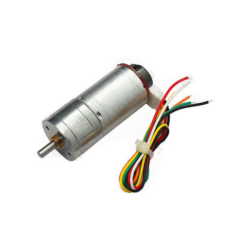
25GA-370 12V 12RPM DC Reducer Gear Motor with Encoder
A 12 V gear motor with encoder — pair it with an L298N or TB6612FNG driver board and implement closed-loop speed control for precise robotics movement.
5. Derating: The Safety Margin Rule
Datasheet ratings are measured under ideal conditions: the IC mounted on a large copper ground plane, ambient temperature of 25°C, with good airflow. In a compact robot chassis with PCBs stacked on top of each other and ambient temperatures of 35–40°C (common in Indian workshops in summer), the effective current capacity drops significantly.
The industry-standard practice is to derate to 60–75% of the rated continuous current for reliable operation:
- L298N rated at 2 A → design for 1.2–1.5 A maximum
- TB6612FNG rated at 1.2 A → design for 0.7–0.9 A maximum
- DRV8833 rated at 1.5 A → design for 0.9–1.1 A maximum
If your motor’s stall current exceeds the derated limit, either choose a higher-rated driver or add a current-limiting circuit in firmware.
6. Driving Multiple Motors
Many projects drive four or more motors. Several strategies exist:
Multiple Driver Modules in Parallel Logic
Using two L298N modules to drive four motors is perfectly fine. Connect both modules to the same Arduino PWM and direction pins (or use separate pins). Each module handles its own pair of motors independently. Ensure both modules share a common ground with the Arduino.
Dedicated Multi-Motor ICs
The L293D has four half-bridges internally, enabling two full H-bridges in one IC. However, the current limit applies per channel, not per IC. The DRV8835 and similar ICs also offer two H-bridges. For four motors, use two such ICs.
Motor Driver Shields
Arduino motor shields (like the Adafruit Motor Shield V2 using PCA9685 + TB6612) drive up to four DC motors. These simplify wiring but add I2C communication overhead and cost. Verify the shield’s current limits before connecting high-current motors.
Common Ground Rule
This is the most frequently violated wiring rule: all grounds — Arduino, motor driver logic, motor driver power, and battery — must be connected together. Without a common ground, logic signals are meaningless and the driver may behave erratically or not at all.
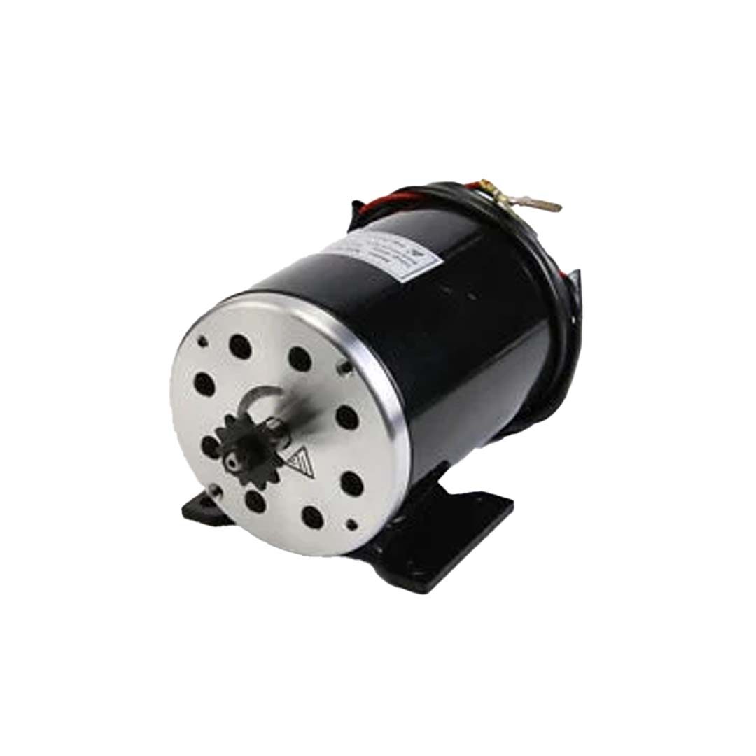
Ebike 500W 24V DC 2500 RPM Motor (MY1020)
For high-power go-kart and e-bike builds running at 24 V and drawing 20+ amps, you need a BTS7960-based high-current driver, not an L298N. This motor demonstrates when driver selection becomes critical.
7. Thermal Management
Heat is the primary killer of motor driver ICs. Every watt dissipated inside the package must escape through the package thermal resistance (θJA) to ambient air.
L298N Heatsink
The L298N in its TO-220 package has θJA of ~50°C/W without a heatsink, 5–10°C/W with a proper finned aluminium heatsink. At 2 A and 2.5 V drop = 5 W dissipation, the junction temperature without a heatsink would be 25 + 50×5 = 275°C — far above the 150°C maximum. A heatsink is not optional; it is essential.
The L298N module includes a small heatsink tab. Attach an aluminium finned heatsink with thermal paste for any sustained load above 1 A per channel.
L293D Heat Mitigation
The L293D in its DIP-16 package has poor thermal resistance and no metal tab. If you must use it near its current limits, force airflow across it with a small fan, or switch to a more efficient driver.
MOSFET Drivers Run Cool
TB6612FNG, DRV8833, and BTS7960 dissipate dramatically less heat. The TB6612FNG at 1 A loses only 0.5 W (0.5 V × 1 A), keeping junction temperature within safe limits without any heatsink. This is why MOSFET drivers dominate modern designs despite costing slightly more.
8. Protection Circuits
Flyback Diodes
Inductors (motor windings) generate a reverse voltage spike when current is switched off. Without flyback (freewheel) diodes, these spikes damage the driver transistors. The L293D includes integrated flyback diodes; the L298N module PCB typically adds them externally. For discrete driver circuits, add 1N4007 or Schottky diodes (faster, preferred) across each motor terminal to the supply rails.
Capacitors on Power Supply
Place a 100 µF electrolytic capacitor across the motor power supply terminals of the driver board. Motor startup current surges can cause supply voltage dips that reset microcontrollers. The capacitor buffers these transients.
Current Sensing
Adding a 0.1–0.5 Ω sense resistor in series with the motor enables firmware-level current monitoring. Read the voltage across the sense resistor with an ADC pin. If current exceeds a threshold for more than a set time, reduce PWM duty cycle or cut power. This software current limiting protects both the driver and the motor from overloads without requiring additional hardware ICs.
Thermal Shutdown
Most modern motor driver ICs include internal thermal shutdown (typically at 150°C junction temperature). This is a last-resort protection, not a design feature to rely on. By the time thermal shutdown triggers, you are already operating outside the component’s reliable operating region.
9. Step-by-Step Selection Guide
Follow these steps every time you select a motor driver:
- Find your motor’s stall current — from the datasheet or by measurement. Add 20% margin.
- Find your motor’s operating voltage — and note your battery voltage.
- Calculate required driver current rating — stall current ÷ 0.7 (derating factor).
- Add voltage drop — if using BJT-based drivers, add 2.5–3.5 V to required supply voltage.
- Count motor channels — ensure the driver has enough H-bridges or plan for multiple modules.
- Check logic voltage compatibility — 5 V Arduino logic vs 3.3 V ESP32/STM32 logic.
- Plan thermal management — calculate power dissipation, determine if a heatsink is required.
- Add flyback diodes and power supply capacitor — as a matter of course.
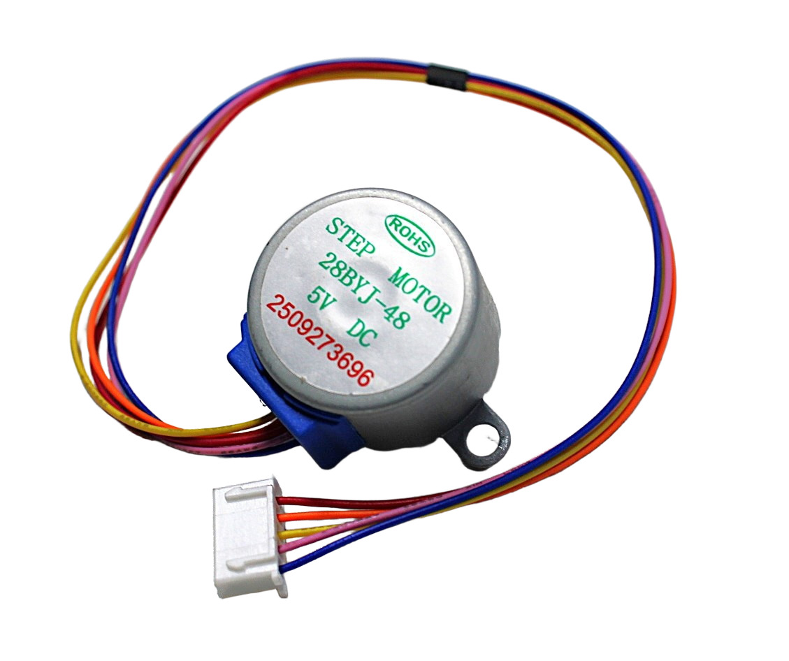
28BYJ-48 5V Stepper Motor
The 28BYJ-48 stepper draws about 200–350 mA per phase and works with the dedicated ULN2003 driver — a great example of matching driver to motor: unipolar stepper, unipolar driver.
Frequently Asked Questions
Can I connect a motor directly to an Arduino pin?
Never. Arduino GPIO pins source at most 40 mA and the total port current is limited to about 200 mA. A motor’s stall current can be 10–50× higher. Connecting a motor directly will damage the Arduino’s ATmega microcontroller permanently.
My L298N module gets very hot — is that normal?
Some warmth is normal. If the heatsink is too hot to touch (above ~60°C case temperature) the IC junction is likely approaching its thermal limit. Add a larger heatsink with thermal paste, reduce duty cycle if the application allows, or switch to a MOSFET-based driver like the TB6612FNG.
Can I drive a 12V motor with an L298N using a 12V power supply?
Yes, but the motor will only receive about 9–10 V due to the L298N’s internal voltage drop. For rated 12 V motor performance, supply the L298N with 14–15 V. Alternatively, use a TB6612FNG which has minimal drop and the motor will receive close to the full supply voltage.
What happens if I exceed the driver’s current rating?
The IC junction temperature rises above its maximum rating. Internal thermal shutdown may activate (if the IC has it), or the junction will permanently fail — typically appearing as a short circuit that then damages the power supply, battery, or other connected components.
Is the L298N still relevant in 2026?
Yes, for applications where cost is the primary constraint and efficiency is not critical. The L298N module (under ₹100 in India) remains the most widely used motor driver in student projects. For any application where battery life or heat management matters, switch to a TB6612FNG or DRV8833.
How do I control motor speed with PWM?
PWM (Pulse Width Modulation) varies the average voltage delivered to the motor by rapidly switching it on and off. At 50% duty cycle, the motor receives approximately half the supply voltage. Connect PWM output pins from your microcontroller to the enable pins (EN) of the motor driver. Use PWM frequencies of 1–25 kHz; too low causes audible noise, too high can exceed the driver’s switching capability.
Conclusion
The golden rule of motor driver selection is simple: your driver’s continuous current rating must exceed your motor’s stall current, with a safety margin applied. Account for voltage drop if using BJT-based drivers. Plan for thermal dissipation. Add flyback diodes and power supply capacitors as standard practice.
For most student and hobbyist projects: the TB6612FNG is the best all-around choice for motors under 2 A. The L298N module works well for TT-motor cars if you add a heatsink and account for voltage drop. Step up to BTS7960-based modules for anything above 5 A.
Find the right motor and driver at Zbotic: Shop DC gear motors, stepper motors, and motor driver modules at zbotic.in/product-category/motors-drivers-pumps-actuators/. We stock L293D, L298N, TB6612, DRV8833, and more with fast delivery across India.


Add comment