
You’re testing your robot or motor project and after a few minutes you notice a burning smell, the motor slows down, or the driver shuts off entirely. When you touch the motor driver IC, it’s scorching hot. Motor driver overheating is one of the most common problems in hobbyist electronics, and it causes project failures, burned components, and occasionally fires.
This comprehensive troubleshooting guide covers exactly why motor drivers get hot, how to identify the severity, and the step-by-step solutions — from hardware fixes to code changes — for the most common drivers used in India: L298N, A4988, DRV8825, TB6612FNG, and BLDC ESCs.
Why Motor Drivers Generate Heat
Every motor driver IC contains internal transistors (MOSFETs or bipolar transistors) that switch motor current. Heat is generated in two ways:
- Conduction losses: When current flows through the transistor, there’s a voltage drop across it (due to its on-resistance R_DS(on) or V_CE(sat)). Power lost = I² × R_on. The higher the current and the higher the internal resistance, the more heat.
- Switching losses: Every time the transistor switches on or off (during PWM), it momentarily passes through a linear region where both current and voltage are high simultaneously. Higher PWM frequency = more switching events per second = more switching loss.
Both types of loss dissipate as heat in the driver IC package. The thermal design of the IC — the junction-to-case thermal resistance (θJC) and the package size — determine how quickly this heat gets to the environment.
The L298N Problem
The L298N uses bipolar transistors (not MOSFETs). Its saturation voltage V_CE(sat) is approximately 2V per transistor pair. At 1A, this means 2W of power loss per H-bridge side. At 2A, it’s 8W. This is why the L298N runs hot even at moderate currents — it’s fundamentally an inefficient design by modern standards. The newer alternatives (TB6612FNG, DRV8833) use MOSFETs and lose less than 0.5V, consuming dramatically less power as heat.
Warning Signs Your Driver Is Overheating
- Thermal shutdown: The driver shuts off automatically when the junction temperature exceeds its thermal protection threshold (typically 150°C internal). The motor suddenly stops, then works again after cooling. This cycles repeatedly.
- Motor slowing without load change: As the driver heats up, its internal resistance increases, reducing the effective voltage to the motor. You’ll notice the motor spinning slower over time.
- Burning smell: Overheated PCB substrate or solder mask releases a distinct burning plastic smell. Immediate action required.
- IC discolouration: Brown or black discolouration on or around the driver IC indicates past overheating damage. The component may be permanently degraded.
- Random resets / brownouts: If the driver’s power supply is shared with the microcontroller, high driver current can cause voltage drops that reset the MCU — another symptom of an overloaded driver circuit.
Temperature guide: A brief touch (1–2 seconds) — slightly warm (up to ~50°C) is normal. Hot but holdable (~60–70°C) is concerning. Too hot to touch (>80°C) is dangerous and risks failure. Use a cheap IR thermometer (₹300–₹500) to measure accurately without touching.
7 Root Causes of Motor Driver Overheating
1. Current Exceeds the Driver’s Rating
This is the most common cause. Every driver has a maximum continuous current rating. Exceeding it even slightly causes exponential heat increase (P = I² × R). Always check your motor’s stall current against the driver’s continuous current rating — not the peak rating.
- L298N: 2A continuous (in practice, ~1.5A with no heatsink at room temperature)
- A4988: 1A continuous without heatsink, 2A with heatsink
- DRV8825: 1.5A continuous without heatsink, 2.2A with heatsink
- TB6612FNG: 1.2A continuous, 3.2A peak
2. Motor Stall or High Starting Current
Stall current (when the motor is mechanically stopped) is typically 3–10× the rated running current. Even momentary stalls during startup or mechanical jam can briefly push the driver far beyond its thermal capacity. If your application involves frequent stops against a hard stop or heavy inertia starts, this repeated high-current burst accumulates heat.
3. Supply Voltage Too High
Higher supply voltage means higher switching losses in the driver’s transistors. It also means more energy dissipated in the driver’s internal voltage regulators or protection circuits. Always stay within the driver’s rated voltage range.
4. PWM Frequency Too High
For bipolar transistor drivers like the L298N, very high PWM frequencies (above ~10–20kHz) don’t improve motor performance but significantly increase switching losses. The transistors can’t switch fast enough and spend more time in the linear region.
5. Inadequate Heatsinking
The L298N module’s included heatsink tab is designed to be bolted to a chassis or fitted with an adhesive heatsink. Without a proper heatsink, even the rated 2A will cause the IC to overheat within minutes at full load.
6. Poor Ventilation / Enclosure
Running a driver inside a sealed enclosure without airflow traps heat. In India’s summer temperatures (often 38–45°C ambient), an enclosure can reach 55–65°C before the motor even starts, leaving very little thermal headroom for the driver IC.
7. Incorrect A4988 Current Trimmer Setting
For the A4988 stepper driver, the on-board trimmer potentiometer sets the maximum motor current via a voltage reference. Many builders leave this at maximum, delivering far more current than their motor needs. An NEMA17 motor rated for 1.2A running at 2A will overheat the driver AND reduce motor torque (steppers lose torque above their rated current due to inductance effects).
Fix 1: Reduce Motor Current
For Stepper Motor Drivers (A4988, DRV8825)
Calculate the correct Vref voltage for your motor’s rated current using:
Vref = I_rated × 8 × R_sense
For A4988 with 0.1Ω sense resistors: Vref = I_rated × 0.8
Example: 1.2A motor → Vref = 1.2 × 0.8 = 0.96V
Measure Vref at the trimmer pot wiper pin with a multimeter and adjust until you reach the target voltage. Reduce to 70% of rated current (use full-step mode) if you don’t need maximum holding torque.
For DC Motor Drivers (L298N, TB6612FNG)
Use PWM duty cycle to limit effective current. Instead of running at 100% PWM, run at 70–80% for your application’s normal speed — this reduces average current and heat. Implement current sensing with a shunt resistor + op-amp or use a driver with built-in current limiting (DRV8871, DRV8833).
Fix 2: Add a Heatsink
For L298N
The L298N IC has a metal tab on top specifically for heatsink attachment. Options:
- Adhesive aluminium heatsink (the small TO-220 package heatsinks, ~₹5–₹20 each) — significant improvement
- Small fan directed at the driver module — reduces temperature by 15–25°C
- Thermal pad + larger aluminium plate — for continuous high-current operation
For A4988 / DRV8825
These come on small PCBs. Stick a small adhesive heatsink directly on the driver IC. Also ensure the PCB itself can dissipate heat through its copper pours — mount it to a metal surface with a thermal pad if possible for high-current stepper use.
Thermal Paste vs Thermal Pad
Use thermal paste for bolted heatsinks on metal tabs. Use adhesive thermal pads for attaching heatsinks to IC packages where paste would be inconvenient. Both work; the difference is minor for small drivers.
Fix 3: Match Supply Voltage Correctly
Many builders use 12V because “it’s available” even when their motors are rated for 6V or 9V. Higher voltage means the driver works harder to regulate the current. Match voltage to your motor’s rating:
- 6V motors: use 6–7.5V supply
- 12V motors: use 12V supply
- For stepper motors: slightly higher than rated coil voltage is fine (the driver’s current limiting handles it), but excessive voltage (>2× rated) increases heat unnecessarily
For the L298N specifically: the enable-pin PWM duty cycle controls motor speed, but the motor supply rail is direct. Using 12V for a 6V motor at full PWM will over-volt the motor — use PWM to compensate, but this increases driver heating. Better: use the correct voltage.
Fix 4: Optimise PWM Frequency
| Driver | Recommended PWM Frequency | Notes |
|---|---|---|
| L298N | 1–10 kHz | Below audible range at 20kHz but more heat; 1kHz is typical |
| TB6612FNG | 100 Hz – 100 kHz | MOSFET-based, handles high frequency well |
| A4988 | Internal (16 kHz) | Fixed internal PWM for current chopping, step rate is external |
| BLDC ESC | 8–32 kHz | Configured in ESC firmware; higher = smoother but more heat |
For Arduino’s default PWM (pins 3,9,10,11 at 490Hz; pins 5,6 at 980Hz): these are fine for L298N. Do not try to use analogWrite with the L298N at 31kHz unless you’ve confirmed the IC can handle it.
Fix 5: Upgrade to a Better Driver IC
If you’ve tried the above and the L298N is still running too hot for your current needs, it’s time to upgrade. Modern MOSFET-based drivers are simply better in every way:
| Driver | Type | Cont. Current | Efficiency | Best For |
|---|---|---|---|---|
| L298N | Bipolar | 2A | ~70% | Learning, low-power motors |
| TB6612FNG | MOSFET | 1.2A | ~95% | Direct L298N replacement, cooler |
| A4988 | MOSFET | 2A | ~90% | NEMA steppers in 3D printers, CNC |
| DRV8825 | MOSFET | 2.2A | ~92% | High-current steppers, 1/32 microstepping |
| BTS7960 (IBT-2) | MOSFET | 43A | ~98% | High-current DC motors, e-bikes |
Motor Driver Comparison Table
Quick reference for the most common overheating scenarios and recommended solutions:
| Scenario | Likely Cause | Fix |
|---|---|---|
| L298N hot at 1A | Normal — inherent inefficiency | Add heatsink, or switch to TB6612FNG |
| A4988 hot immediately | Vref too high | Measure and reduce Vref |
| Driver thermal shuts off under load | Motor current too high | Upgrade driver or add heatsink + fan |
| Driver hot even at idle | Quiescent current or short | Check wiring; verify motor not stalled |
| BLDC ESC very hot | Motor overloaded or propeller wrong size | Reduce prop size; check motor KV vs battery |
Recommended Motor Drivers from Zbotic

A4988 Stepper Motor Driver Controller Board (Red)
Highly efficient MOSFET-based stepper driver with adjustable current limiting — set Vref correctly and it runs cool even at 2A with a small heatsink.
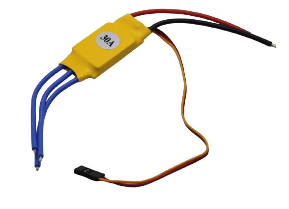
30A BLDC ESC Brushless Electronic Speed Controller
Rated 30A continuous for brushless DC motors — proper thermal design with adequate current rating prevents the overheating that plagues undersized ESCs.

NEMA17 5.6 kg-cm Stepper Motor with Detachable Cable
A well-specified stepper motor with datasheet-accurate current ratings — pair with A4988 and set Vref correctly to achieve cool, reliable operation.
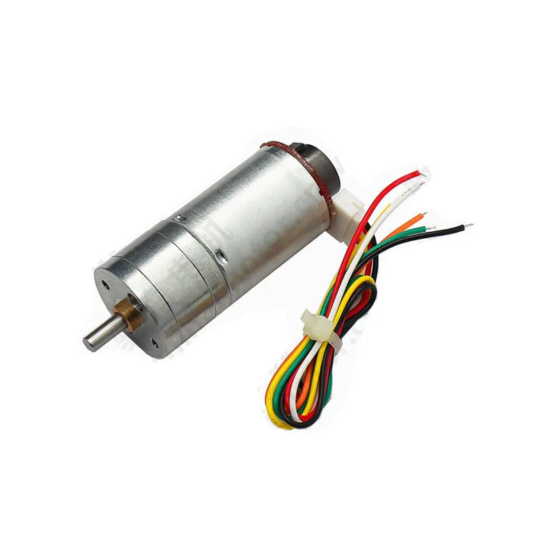
25GA-370 12V 12RPM DC Gear Motor with Encoder
Low-current gear motor — the built-in gearbox means the motor itself draws less current for the same output force, directly reducing driver heat compared to ungeared motors.
Frequently Asked Questions
Q1: Is it normal for the L298N to get warm during normal operation?
Yes — warm is normal (40–60°C). Hot to the touch (70–80°C) is a warning sign. Untouchable (>85°C) is a problem. The L298N is an inherently inefficient design that produces more heat than modern MOSFET drivers. Adding a heatsink and ensuring you don’t exceed 1.5A per channel will keep it in the warm-but-safe range for most applications.
Q2: My A4988 driver has no trimmer pot — how do I set the current?
Some budget A4988 modules have the pot preset at maximum. You can measure Vref at the exposed test point on the board. If it’s set too high, carefully rotate the trimmer (tiny brass screw) counter-clockwise to lower Vref. Use a multimeter and make small adjustments, remeasuring after each turn. Target: Vref = (rated motor current) × 0.8 for A4988 with 0.1Ω sense resistors.
Q3: Can I use multiple L298N modules in parallel to handle more current?
No — never parallel motor driver outputs. The slight difference in internal resistance will cause one driver to carry disproportionately more current. Instead, use a single higher-rated driver (BTS7960 for high current DC motors) or separate drivers for separate motors.
Q4: My BLDC ESC overheats after 30 seconds — what’s wrong?
For brushless motor ESCs, overheating is almost always one of: (1) ESC rated amperage is too low for the motor’s actual draw — measure with a current meter and upgrade to a higher-rated ESC; (2) motor KV is wrong for the propeller — use a lower KV motor or smaller prop; (3) ESC PWM frequency set too high in firmware; (4) inadequate airflow over the ESC — mount it in the airstream of the propeller for cooling.
Q5: How do I add current limiting to protect a cheap motor driver?
The easiest software-level protection: monitor motor current using a shunt resistor + ACS712 current sensor module. Read the current in your main loop and if it exceeds your threshold (e.g., 80% of driver rated current), reduce PWM duty cycle or trigger an emergency stop. This won’t replace proper hardware thermal protection but adds a layer of software safety.
Q6: After my L298N overheated, the motor barely runs now — is the driver damaged?
Possibly. Repeated thermal cycling can degrade the internal transistors. Test by measuring the output voltage with a known good small motor at low duty cycle. If output is significantly lower than expected, or the driver shows erratic behaviour, it’s likely damaged. L298N modules are inexpensive — replace it rather than continue using a suspect component.
Conclusion
Motor driver overheating is almost always preventable. The root cause is nearly always one of three things: the driver is carrying more current than it’s rated for, inadequate heat dissipation is causing normal losses to accumulate, or an inefficient driver technology (like the L298N’s bipolar design) is generating more heat than modern alternatives would.
The action plan: measure your motor’s actual current draw with a meter (not just the spec sheet), add a heatsink to any driver that runs continuously, set the A4988 Vref correctly for your motor, and if you outgrow the L298N, upgrade to a TB6612FNG or BTS7960 depending on your current requirements. With the right driver, properly rated, you should never see thermal shutdown in normal operation.
Find the Right Motor Driver for Your Project
Shop properly-rated motor drivers, stepper drivers, and ESCs at Zbotic — delivered fast across India with no import hassles.


Add comment