
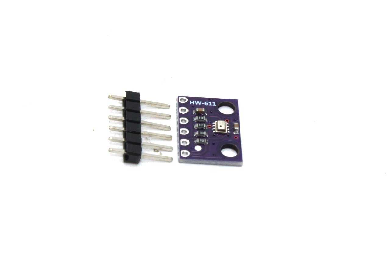
The MLX90640 is a remarkable little sensor from Melexis that packs a 32×24 array of infrared thermopile pixels into a compact SMD package. Unlike single-pixel IR sensors (such as the MLX90614), the MLX90640 gives you a true 2D thermal image — 768 temperature readings per frame — updated at up to 64 frames per second. It is not a competition for professional FLIR cameras, but for electronics hobbyists, engineers, and researchers, it enables genuine thermal imaging at a fraction of the cost. This guide walks you through everything you need to know to build a live heat map display with the MLX90640.
1. MLX90640 Overview and Specifications
The MLX90640 is a far-infrared (FIR) sensor array with a measurement range of -40°C to +300°C, making it suitable for everything from body temperature scanning to electronics thermal profiling to detecting hot pipes and electrical faults. Key specifications:
| Parameter | Value |
|---|---|
| Array size | 32 × 24 pixels (768 pixels total) |
| Temperature range | -40°C to +300°C |
| Accuracy | ±1°C (0°C to 50°C), ±2°C (full range) |
| Frame rate | Up to 64 Hz (practical: 8–16 Hz on Arduino) |
| Interface | I2C (up to 1 MHz fast-mode) |
| Supply voltage | 3.3V (3.0V–3.6V range) |
| I2C address | 0x33 (default, configurable) |
| Field of view | 110°×75° (wide) or 55°×35° (standard) |
The sensor communicates over I2C and internally stores factory calibration data (EEPROM) used to convert raw pixel ADC values into calibrated temperatures. The MLX90640 library reads this EEPROM data and performs the compensation calculations — you don’t need to implement the maths yourself.
2. Field of View: Wide vs Standard Angle
The MLX90640 comes in two field-of-view (FoV) variants:
- MLX90640-D110 (110°×75°): Wide angle. Covers a broad area at close range. Good for room occupancy detection, people counting, or building HVAC monitoring where you want to see a wide area at once.
- MLX90640-D055 (55°×35°): Standard (narrow) angle. Better for focused inspection of equipment, PCB thermal profiling, or identifying hotspots on a specific target. Better spatial resolution on the target at the expense of coverage area.
For a rough estimate of coverage: at 1 metre distance, the 110° version covers approximately 2m × 1.4m. Each pixel subtends about 3.4° × 3.1°. This gives a spatial resolution at 1m of roughly 6cm per pixel — adequate for detecting hot spots on a laptop or checking whether a person is in the room, but not for fine detail.
3. Components Needed
- MLX90640 breakout board (Pimoroni, Adafruit, or bare module on a PCB with I2C pull-ups)
- Arduino Mega 2560 (preferred — more RAM than Uno; the 768-pixel float array is memory-intensive), or Raspberry Pi, or ESP32
- Colour TFT display (ILI9341 2.4″, 320×240 pixels recommended for a nice heat map)
- 3.3V power source for the MLX90640 (most breakout boards include a 3.3V regulator if powering from 5V Arduino)
- 4.7kΩ I2C pull-up resistors (already on most breakout boards)
- Breadboard and jumper wires
Important: The Arduino Uno has only 2KB of SRAM, which is barely enough to hold the 768-float temperature array (3072 bytes). An Arduino Mega with 8KB SRAM is much more comfortable. An ESP32 or Raspberry Pi is ideal for high frame rate applications.
4. Wiring the MLX90640 to Arduino or Raspberry Pi
The MLX90640 is a 3.3V device. Connect it to Arduino as follows (using a breakout board with 3.3V regulator):
| MLX90640 Breakout | Arduino Mega | Raspberry Pi |
|---|---|---|
| VIN / 3.3V | 3.3V | Pin 1 (3.3V) |
| GND | GND | Pin 6 (GND) |
| SDA | Pin 20 (SDA) | Pin 3 (GPIO2/SDA) |
| SCL | Pin 21 (SCL) | Pin 5 (GPIO3/SCL) |
The I2C bus for the MLX90640 should ideally run at 400 kHz (fast mode) or 1 MHz (fast-mode plus) for reasonable frame rates. At 100 kHz standard mode, reading 768 pixels over I2C takes roughly 60ms, limiting you to about 16 fps — which is still usable. On Arduino, call Wire.setClock(400000) after Wire.begin() to enable 400 kHz I2C.
5. Arduino Setup and Library Installation
Install the Adafruit MLX90640 library via the Arduino Library Manager (search “MLX90640”). This library handles EEPROM read, calibration parameter extraction, and temperature calculation.
#include <Wire.h>
#include <Adafruit_MLX90640.h>

Adafruit_MLX90640 mlx;
float frame[32 * 24]; // 768 temperature readings

void setup() {
  Serial.begin(115200);
  Wire.begin();
  Wire.setClock(400000); // 400 kHz I2C

  if (!mlx.begin(MLX90640_I2CADDR_DEFAULT, &Wire)) {
    Serial.println("MLX90640 not found! Check wiring.");
    while (1);
  }

  mlx.setMode(MLX90640_CHESS);         // Chess pattern readout (better uniformity)
  mlx.setResolution(MLX90640_ADC_18BIT);
  mlx.setRefreshRate(MLX90640_8_HZ);   // 8 frames per second

  Serial.println("MLX90640 Ready");
  Serial.print("Serial number: ");
  Serial.print(mlx.serialNumber[0], HEX);
  Serial.print(mlx.serialNumber[1], HEX);
  Serial.println(mlx.serialNumber[2], HEX);
}
The MLX90640_CHESS mode reads odd and even rows in alternating frames (interleaved patterns), providing better uniformity than the default TV-scan mode. Set the refresh rate to match your application — 1 Hz for slow thermal surveys, 8 Hz for comfortable real-time display, up to 32 Hz for faster tracking.
6. Displaying a Heat Map on Serial Plotter
The simplest visualisation is ASCII art in the Serial Monitor. Map temperature to a character based on heat level:
const char* tempToChar(float t) {
  if (t < 20) return " ";
  if (t < 25) return ".";
  if (t < 30) return "-";
  if (t < 35) return "=" ;
  if (t < 40) return "+";
  if (t < 45) return "*";
  return "#";
}

void loop() {
  if (mlx.getFrame(frame) != 0) {
    Serial.println("Frame error");
    return;
  }
  for (int y = 0; y < 24; y++) {
    for (int x = 0; x < 32; x++) {
      Serial.print(tempToChar(frame[y * 32 + x]));
      Serial.print(" ");
    }
    Serial.println();
  }
  Serial.println("---");
}
This produces a 32×24 ASCII heat map in the serial terminal. While primitive, it immediately reveals thermal gradients and hotspots — surprisingly useful for debugging PCB heat distribution or checking if a heatsink is working.
7. Heat Map on a Colour TFT Display
For a genuine colour heat map, pair the MLX90640 with an ILI9341 colour TFT display. Install the Adafruit ILI9341 and Adafruit GFX libraries. The strategy is to map each pixel temperature to a colour using the classic iron/rainbow palette:
#include <Adafruit_ILI9341.h>
#include <SPI.h>

#define TFT_CS  10
#define TFT_DC   9
#define TFT_RST  8
Adafruit_ILI9341 tft = Adafruit_ILI9341(TFT_CS, TFT_DC, TFT_RST);

// Simple iron palette: blue → cyan → green → yellow → red
uint16_t tempToColor(float t, float tMin, float tMax) {
  float ratio = constrain((t - tMin) / (tMax - tMin), 0.0, 1.0);
  uint8_t r, g, b;
  if (ratio < 0.25) {
    b = 255; g = (uint8_t)(ratio * 4 * 255); r = 0;
  } else if (ratio < 0.5) {
    b = (uint8_t)((0.5 - ratio) * 4 * 255); g = 255; r = 0;
  } else if (ratio < 0.75) {
    b = 0; g = 255; r = (uint8_t)((ratio - 0.5) * 4 * 255);
  } else {
    b = 0; g = (uint8_t)((1.0 - ratio) * 4 * 255); r = 255;
  }
  return tft.color565(r, g, b);
}

void drawHeatmap(float minT, float maxT) {
  // Scale 32x24 pixel array to 320x240 display (10x scale)
  for (int y = 0; y < 24; y++) {
    for (int x = 0; x < 32; x++) {
      uint16_t color = tempToColor(frame[y * 32 + x], minT, maxT);
      tft.fillRect(x * 10, y * 10, 10, 10, color);
    }
  }
}

void loop() {
  if (mlx.getFrame(frame) != 0) return;
  float minT = frame[0], maxT = frame[0];
  for (int i = 1; i < 768; i++) {
    if (frame[i] < minT) minT = frame[i];
    if (frame[i] > maxT) maxT = frame[i];
  }
  drawHeatmap(minT, maxT);
  // Draw min/max temps
  tft.setTextColor(ILI9341_WHITE, ILI9341_BLACK);
  tft.setCursor(0, 242);
  tft.print(minT, 1); tft.print("C  ");
  tft.print(maxT, 1); tft.print("C");
}
Each MLX90640 pixel is scaled to a 10×10 pixel block on the 320×240 TFT, filling the display perfectly. The colour gradient auto-scales to the current min/max temperature, making hotspots visible even if the absolute temperature range is narrow.
8. Raspberry Pi Python Implementation
On a Raspberry Pi, the Python ecosystem provides a smoother path to real-time colour display. Install the library with pip3 install adafruit-circuitpython-mlx90640 and enable I2C via raspi-config.
import board
import busio
import adafruit_mlx90640
import matplotlib.pyplot as plt
import numpy as np

i2c = busio.I2C(board.SCL, board.SDA, frequency=400000)
mlx = adafruit_mlx90640.MLX90640(i2c)
mlx.refresh_rate = adafruit_mlx90640.RefreshRate.REFRESH_8_HZ

frame = [0] * 768
fig, ax = plt.subplots()
plt.ion()

while True:
    try:
        mlx.getFrame(frame)
        data = np.array(frame).reshape(24, 32)
        ax.clear()
        im = ax.imshow(data, cmap='inferno', vmin=15, vmax=40)
        plt.colorbar(im, ax=ax)
        ax.set_title(f'Thermal Image — Max: {data.max():.1f}°C')
        plt.pause(0.1)
    except ValueError:
        pass
Matplotlib’s inferno colormap (black → red → yellow → white) is the most visually intuitive for thermal imaging. Run this script on a Raspberry Pi with a connected monitor or over VNC for a live thermal camera display.
9. Real-World Applications
The MLX90640 is not just a hobbyist curiosity — it has genuine professional applications:
- PCB thermal profiling: Point the sensor at a running PCB to identify hotspots — overloaded regulators, bad solder joints with high resistance, or improperly heatsinked components.
- HVAC fault detection: Scan air ducts, pipes, and insulation for temperature anomalies indicating blockages, leaks, or insulation failures.
- Human presence detection: At 8 fps, the MLX90640 reliably detects human body heat. Use it for smart lighting control, occupancy counting, or intruder detection without the privacy concerns of a camera.
- Food safety monitoring: Monitor cooking temperature distribution on a hot plate or grill without contact thermometers.
- Electrical panel inspection: Scan circuit breakers, fuses, and bus bars for hot spots indicating overload or loose connections.
- 3D printer bed levelling: Map the thermal uniformity of a heated print bed to identify areas that are warping the first layer.
10. Limitations and How to Work Around Them
Low spatial resolution: 32×24 pixels is very coarse for detailed inspection. Work closer to the target — at 20cm, each pixel covers about 1.2cm. For fine detail, consider the MLX90641 (16×12 but cheaper) or invest in a FLIR Lepton module (80×60 pixels) as a step up.
Slow refresh rate on Arduino: Uno/Nano struggle with the I2C bandwidth and memory. Use a Mega, ESP32, or Raspberry Pi for smooth real-time display. The ESP32’s built-in I2C at 400 kHz and 520KB SRAM makes it an ideal host.
Emissivity variation: The sensor assumes an emissivity of 1.0 (perfect blackbody). Shiny metal surfaces have much lower emissivity (aluminium ~0.05) and will read far too cold. Apply matt black tape or paint to metallic targets for accurate readings, or apply emissivity correction in software.
Ambient temperature sensitivity: The sensor includes a built-in ambient temperature sensor used for calibration. Shield the sensor from direct airflow and heat sources that could create a false temperature gradient across the array.
BMP280 Barometric Pressure and Altitude Sensor
Combine this I2C barometric pressure and temperature sensor with the MLX90640 to add ambient environmental context to your thermal imaging station.
Frequently Asked Questions
Can the MLX90640 measure body temperature for fever screening?
The MLX90640 can detect that a person has elevated skin temperature, but medical-grade fever screening requires much higher accuracy (±0.1°C) than the sensor provides. Distance, emissivity variation (skin vs clothing), and ambient conditions all introduce errors. The MLX90640 is suitable for indicative detection but not for certified medical triage — do not rely on it as a sole fever screening tool.
Why does my heat map have a pattern of alternating bright and dark rows?
This is a characteristic of interleaved (TV pattern) mode — odd and even rows are read in alternate sub-frames. Switch to MLX90640_CHESS mode, which uses a checkerboard readout pattern and produces much better uniformity. The Adafruit library defaults to chess mode.
What is the maximum I2C cable length for the MLX90640?
At 400 kHz I2C, keep cable length under 30cm for reliable operation with standard 4.7kΩ pull-ups. If you must run longer cable, reduce the I2C clock to 100 kHz and consider using I2C buffers (PCA9600) or I2C-over-UART adapters for cable runs over 1 metre.
Can I connect multiple MLX90640 sensors on the same I2C bus?
The default I2C address is 0x33, and it can be changed to 0x32 or 0x33 by soldering address solder pads on the breakout board. This allows two sensors on one bus. For more sensors, use an I2C multiplexer (TCA9548A) to switch between them individually.
How do I achieve image interpolation for a smoother heat map?
The raw 32×24 image looks blocky when scaled up. Apply bilinear or bicubic interpolation to generate a higher-resolution image. In Python, scipy.ndimage.zoom(data, 8, order=3) upscales to 256×192 using bicubic interpolation, producing a smooth, professional-looking heat map from the raw 32×24 data.
Explore Thermal and Infrared Sensors at Zbotic
From single-pixel IR sensors to full array thermal cameras, Zbotic has the components you need for your next thermal imaging or temperature measurement project.


Add comment