
LCD Backlight Dimming: PWM Control for Power Saving Projects
One of the most effective ways to extend battery life in any embedded project is LCD backlight PWM dimming for power saving. The backlight is often the single largest power consumer on an LCD or TFT display — easily drawing 20 to 80 mA at full brightness. By using Pulse Width Modulation (PWM) to control backlight intensity, Indian makers can dramatically reduce current consumption, improve display visibility in low-light environments, and add professional dimming features to smartwatches, IoT devices, and portable instruments. This comprehensive guide covers every aspect of LCD backlight dimming, from basic transistor circuits to advanced adaptive brightness control.
Why Backlight Dimming Matters for Power Saving
Modern LCD and TFT displays consist of two main power-consuming components: the display controller IC (relatively low power, typically 1–5 mA) and the LED backlight (high power, typically 20–80 mA depending on screen size). In many compact projects, the backlight consumes 60–80% of total system power.
Consider these typical backlight current readings:
- 0.96-inch OLED: No backlight (self-emissive) — not applicable
- 1.28-inch GC9A01 TFT: ~20 mA at full brightness
- 1.8-inch ST7735 TFT: ~25–35 mA at full brightness
- 2.4-inch ILI9341 TFT: ~50–70 mA at full brightness
- 3.5-inch ILI9488 TFT: ~70–100 mA at full brightness
For a project running on a 1000 mAh LiPo battery, a 2.4-inch display at full brightness alone would drain the battery in roughly 14–20 hours. Dimming to 30% brightness reduces that draw to ~15–20 mA, more than tripling battery life. Add an auto-sleep feature (backlight off when no activity), and you can achieve weeks of standby time.
PWM Basics: How Dimming Works
Pulse Width Modulation works by rapidly switching the backlight LED on and off at a frequency too fast for the human eye to detect (typically 500 Hz to 10 kHz). The duty cycle — the percentage of time the signal is HIGH — directly controls the perceived brightness:
- 100% duty cycle = full brightness
- 50% duty cycle = half brightness (about 50% less power)
- 10% duty cycle = very dim (about 10% of max power)
- 0% duty cycle = backlight off
The key advantage of PWM over a simple voltage divider is efficiency: the LED is either fully on or fully off at any instant, so no power is wasted as heat in a resistor.
Choosing PWM Frequency
For most display backlights, a PWM frequency between 1 kHz and 5 kHz is ideal. Too low (below 100 Hz) causes visible flicker, which is both annoying and can cause eye strain. Too high (above 100 kHz) may cause EMI issues and may not be achievable with simple transistor circuits due to switching losses.
Backlight Dimming Circuits
Option 1: Direct PWM Pin (for displays with onboard current limiter)
Many display modules include a current-limiting resistor on the backlight line and expose a BLK (backlight) pin that accepts a direct PWM signal. In this case, simply connect the BLK pin to a PWM-capable GPIO on your microcontroller. Check the datasheet — if the BLK pin is rated for 3.3V logic and the backlight resistor is onboard, no external circuit is needed.
Option 2: NPN Transistor Circuit (most common)
For displays where you need to switch a higher backlight current, use an NPN transistor (e.g., 2N2222, BC547, S8050):
MCU GPIO (PWM) ─── 1kΩ resistor ─── Base (NPN transistor)
                                      |
                                   Collector ─── Backlight LED cathode
                                                  |
                                             Backlight LED anode ─── VCC
NPN Emitter ─── GND
The 1kΩ base resistor limits base current. When the MCU outputs HIGH (PWM), the transistor saturates and passes current through the backlight. When LOW, the transistor cuts off and the backlight turns off.
Option 3: MOSFET Circuit (for high-efficiency, low heat)
For larger displays or when minimum heat dissipation is critical, use an N-channel MOSFET like the IRLZ44N or AO3400:
- Gate → MCU PWM pin (directly for 3.3V logic MOSFETs, or through a 100Ω resistor to limit gate ringing)
- Drain → Backlight LED cathode
- Source → GND
MOSFETs have near-zero gate current requirement and very low Rds(on), making them ideal for battery-powered designs.
Arduino PWM Dimming Code
Arduino’s analogWrite() function generates PWM on designated pins (pins 3, 5, 6, 9, 10, 11 on Uno). The value ranges from 0 (0% duty, off) to 255 (100% duty, full brightness).
Basic Dimming Example
const int BLK_PIN = 9; // PWM pin connected to backlight

void setup() {
  pinMode(BLK_PIN, OUTPUT);
  // Start at full brightness
  analogWrite(BLK_PIN, 255);
}

void loop() {
  // Fade in
  for (int brightness = 0; brightness <= 255; brightness += 5) {
    analogWrite(BLK_PIN, brightness);
    delay(20);
  }
  delay(1000);
  // Fade out
  for (int brightness = 255; brightness >= 0; brightness -= 5) {
    analogWrite(BLK_PIN, brightness);
    delay(20);
  }
  delay(1000);
}
Auto-Dim After Inactivity
const int BLK_PIN = 9;
const int BUTTON_PIN = 2;
const unsigned long DIM_TIMEOUT = 10000; // 10 seconds
const unsigned long SLEEP_TIMEOUT = 30000; // 30 seconds

unsigned long lastActivity = 0;
bool dimmed = false;
bool sleeping = false;

void setup() {
  pinMode(BLK_PIN, OUTPUT);
  pinMode(BUTTON_PIN, INPUT_PULLUP);
  analogWrite(BLK_PIN, 255);
  lastActivity = millis();
}

void loop() {
  // Check for activity (button press)
  if (digitalRead(BUTTON_PIN) == LOW) {
    lastActivity = millis();
    analogWrite(BLK_PIN, 255); // Wake up
    dimmed = false;
    sleeping = false;
  }

  unsigned long elapsed = millis() - lastActivity;

  if (!dimmed && elapsed > DIM_TIMEOUT) {
    analogWrite(BLK_PIN, 50); // Dim to ~20%
    dimmed = true;
  }

  if (!sleeping && elapsed > SLEEP_TIMEOUT) {
    analogWrite(BLK_PIN, 0); // Backlight off
    sleeping = true;
  }
}
ESP32 LEDC PWM Dimming
The ESP32 has a dedicated LEDC (LED Control) peripheral that generates high-resolution PWM on any GPIO pin. Unlike Arduino’s fixed 8-bit PWM, ESP32 LEDC supports up to 16-bit resolution and precise frequency control.
const int BLK_PIN = 15;    // Backlight GPIO
const int LEDC_CHANNEL = 0;
const int LEDC_FREQ = 5000; // 5 kHz
const int LEDC_RES = 8;     // 8-bit = 0-255

void setup() {
  ledcSetup(LEDC_CHANNEL, LEDC_FREQ, LEDC_RES);
  ledcAttachPin(BLK_PIN, LEDC_CHANNEL);
  ledcWrite(LEDC_CHANNEL, 255); // Full brightness
}

void setBacklight(uint8_t brightness) {
  ledcWrite(LEDC_CHANNEL, brightness);
}

void loop() {
  setBacklight(255); // Full
  delay(2000);
  setBacklight(128); // Half
  delay(2000);
  setBacklight(25);  // ~10%
  delay(2000);
  setBacklight(0);   // Off
  delay(1000);
}
On newer ESP32 Arduino core (v3.x), use the simplified API:
// ESP32 Arduino Core v3.x
analogWriteFrequency(BLK_PIN, 5000);
analogWriteResolution(8);
analogWrite(BLK_PIN, brightness);
Adaptive Brightness with Light Sensors
Professional devices adjust backlight brightness based on ambient light — bright in sunlight, dim indoors. You can implement this with a simple LDR (light-dependent resistor) or a BH1750 digital light sensor.
LDR-Based Adaptive Brightness
const int LDR_PIN = A0;  // Analog read
const int BLK_PIN = 9;   // PWM backlight

void loop() {
  int ldrValue = analogRead(LDR_PIN);  // 0–1023
  // Map: bright room (high LDR) = bright backlight
  // Adjust mapping for your LDR voltage divider
  int brightness = map(ldrValue, 0, 1023, 20, 255);
  brightness = constrain(brightness, 20, 255);
  analogWrite(BLK_PIN, brightness);
  delay(100); // Smooth update rate
}
Add a simple low-pass filter to avoid rapid flickering when the light level changes quickly:
static float smoothedBrightness = 255.0;
float targetBrightness = map(analogRead(LDR_PIN), 0, 1023, 20, 255);
smoothedBrightness = 0.95 * smoothedBrightness + 0.05 * targetBrightness;
analogWrite(BLK_PIN, (int)smoothedBrightness);
Real Power Savings: Numbers and Measurements
Let’s look at real-world power savings for a 2.4-inch ILI9341 TFT display running on an ESP32 project:
| Backlight Setting | Backlight Current | Battery Life (1000 mAh) |
|---|---|---|
| 100% (always on) | ~60 mA | ~10–14 hours |
| 50% duty cycle | ~30 mA | ~20–28 hours |
| 20% duty cycle | ~12 mA | ~50–70 hours |
| Sleep (0%) | ~0.5 mA | ~weeks |
These figures assume only the display backlight. Total system power includes the MCU, sensors, and radio modules.
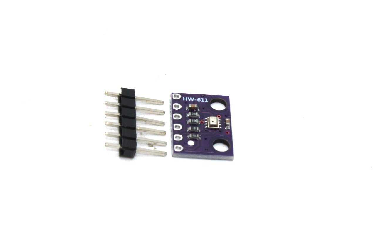
BMP280 Barometric Pressure & Altitude Sensor
Ideal sensor to display on a power-optimized LCD dashboard. Low power consumption (2.7 µA in normal mode) pairs perfectly with dimmed backlight projects.
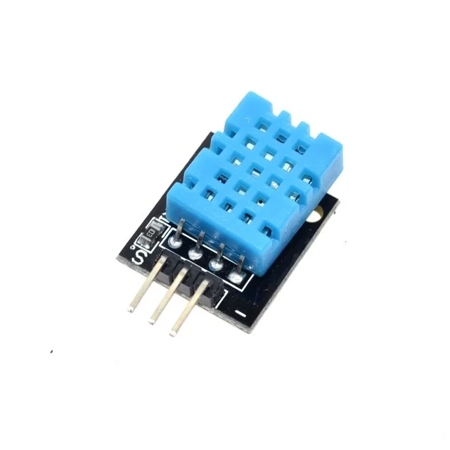
DHT11 Temperature & Humidity Sensor Module
A classic sensor for battery-powered display projects. With PWM backlight dimming, your environmental monitor can last days on a single charge.
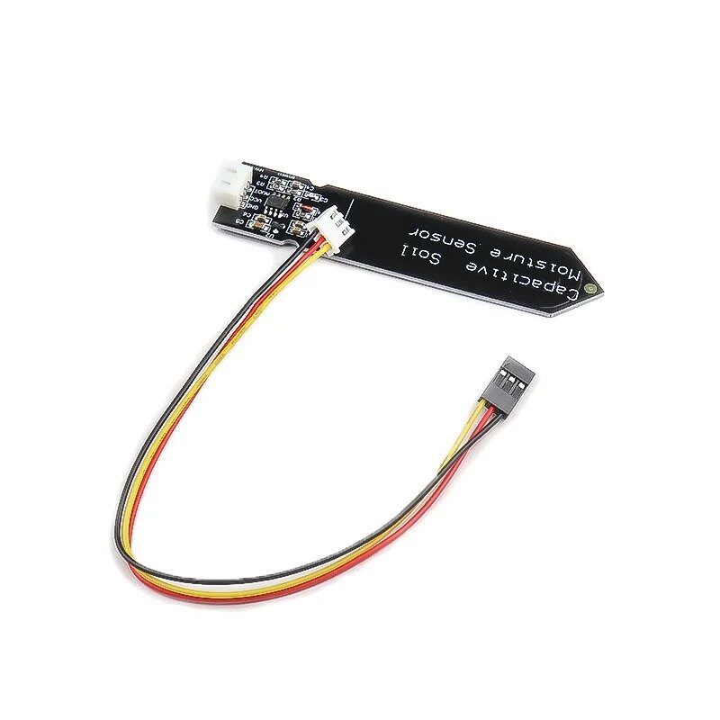
Capacitive Soil Moisture Sensor
Build a solar-powered garden monitor with a dimmed LCD display. Auto-dim when no one is nearby to extend battery life significantly.
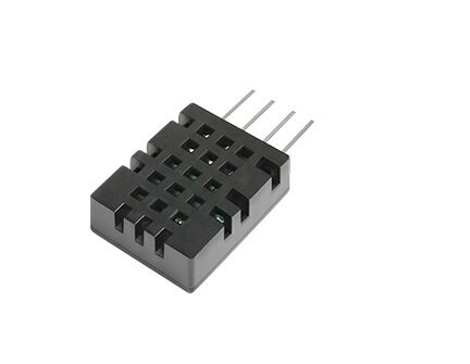
DHT20 SIP Temperature and Humidity Sensor
I2C sensor with improved accuracy for power-conscious LCD display builds. Lower active current than DHT11 means more battery budget for your backlight.

LM35 Temperature Sensor
Ultra-low power analog temperature sensor. Perfect companion for a battery-powered TFT gauge project with PWM backlight control.
Frequently Asked Questions
Q1: Why does my backlight flicker at low duty cycles?
Flicker is visible when the PWM frequency is too low (below 100–200 Hz). Increase the PWM frequency to at least 1 kHz. On Arduino Uno, the default analogWrite() frequency on pins 5 and 6 is ~980 Hz, while pins 3, 9, 10, 11 use ~490 Hz — increase it using the Timer registers or switch to a higher-frequency pin.
Q2: Can I control TFT backlight brightness without an external transistor?
Only if the display module’s BLK pin is designed to accept a direct PWM signal AND the backlight current is within the GPIO’s source current limit (typically 20–40 mA for most MCU pins). If the backlight draws more than 20 mA, you need a transistor or MOSFET to avoid damaging the MCU pin.
Q3: Does PWM dimming affect the display image quality?
No. PWM only controls the backlight LEDs — it has no effect on the LCD panel itself or the image being displayed. The pixels remain at the same brightness relative to the backlight level.
Q4: What PWM frequency should I use for a camera-facing display (to avoid banding)?
Camera sensors can capture PWM flicker as banding in video. Use a PWM frequency that is a multiple of the camera’s frame rate, or use DC dimming if available. For most cameras, 1 kHz or higher reduces banding significantly.
Q5: How much current does a typical TFT backlight use?
Current varies by display size. Small 1.28-inch TFTs use around 15–25 mA, 2.4-inch screens use 50–70 mA, and 3.5-inch screens can use up to 100 mA. Always check your display module’s datasheet or measure with a multimeter.
Build Smarter, Power-Efficient Display Projects
Find sensors, display modules, and components for your next battery-powered maker project at Zbotic.in — India’s premier electronics components store.


Add comment