
Building a I2C OLED multiple Arduino master slave network is one of the most practical ways to add visual feedback to a distributed embedded system. Whether you are building a multi-sensor weather station, a CNC control panel, or an industrial monitoring rig, using multiple Arduinos that share a single OLED display — or each drive their own display over I2C — gives you unmatched scalability at a fraction of the cost. In this guide, we walk through everything from the theory of the I2C bus to the exact Arduino code you need to get your master-slave OLED network running today.
What Is the I2C Protocol and Why Use It?
I2C (Inter-Integrated Circuit) is a two-wire serial communication protocol invented by Philips. It uses a clock line (SCL) and a data line (SDA) to let multiple devices talk on the same bus. In the context of Arduino projects, I2C is the go-to choice for OLED displays because:
- Only two pins needed — frees up GPIO for sensors and actuators.
- Up to 127 devices can share a single bus (with unique addresses).
- Bidirectional communication — the master can both send and receive data.
- Inexpensive and widely supported — SSD1306, SSD1309, and SH1106 OLED modules all support I2C natively.
In a master-slave architecture, one Arduino acts as the I2C master, controlling the bus clock and initiating all communication. The slave Arduinos only respond when addressed. This is perfect for scenarios where a central controller (master) needs to push display data to multiple output nodes (slaves), each with their own OLED screen.
The standard I2C speed is 100 kHz (Standard Mode), though Arduino Wire library supports Fast Mode at 400 kHz. For OLED displays, 400 kHz is generally fine and noticeably improves refresh rate when pushing full-frame updates.
Hardware Setup: Wiring Multiple Arduinos and OLEDs
For a basic master-slave OLED network, you need:
- 1x Master Arduino (Uno, Nano, or Mega)
- 2–4x Slave Arduinos (Nano is ideal for compact builds)
- 1x 0.96-inch or 1.3-inch I2C OLED per slave (SSD1306 or SH1106)
- 4.7 kΩ pull-up resistors on SDA and SCL (if not already on the OLED module)
- Common GND wire connecting all Arduinos
Wiring diagram (text description):
Master Arduino   →   Slave Arduino 1   →   Slave Arduino 2
   A4 (SDA)     →       A4 (SDA)       →      A4 (SDA)
   A5 (SCL)     →       A5 (SCL)       →      A5 (SCL)
   GND          →       GND            →      GND

Each Slave Arduino:
   A4 (SDA)  → OLED SDA
   A5 (SCL)  → OLED SCL
   5V / 3.3V → OLED VCC
   GND       → OLED GND
Important: Pull-up resistors are typically built into most 0.96-inch OLED breakout boards. If you have bare OLED modules without pull-ups, add 4.7 kΩ from SDA to VCC and SCL to VCC at one point on the bus only.
Keep your I2C bus wires short — under 30 cm for reliable 400 kHz operation. For longer runs, use shielded cable or drop back to 100 kHz.
I2C Address Assignment for Multiple Displays
Here is where many beginners hit a wall: by default, most SSD1306 OLED modules ship with address 0x3C. Some have an address solder jumper to switch to 0x3D. So you can only have two OLEDs directly on one I2C bus if they are on the same Arduino.
The solution in a master-slave network is to connect each OLED directly to its slave Arduino, not the master. Each slave’s local I2C bus only has one device (the OLED at 0x3C), so there’s no address conflict. The inter-Arduino communication uses a different I2C channel where the slaves act as I2C slave peripherals to the master.
Two I2C channels on one slave Arduino (Mega only): The Arduino Mega has two hardware I2C ports. You could use Wire (SDA=20, SCL=21) for the master bus and Wire1 (SDA=70, SCL=71) for the OLED. On Uno/Nano, use software I2C (SoftWire library) for the OLED if needed.
For most hobbyist builds, the cleanest architecture is:
- Master Arduino → communicates with slaves via I2C (slaves have addresses 0x08, 0x09, 0x0A, etc.)
- Each Slave Arduino → has its own dedicated I2C bus connected to its local OLED at 0x3C
Master Arduino Code: Sending Display Commands
The master initiates all communication and sends display strings (or structured data packets) to each slave.
#include <Wire.h>

// Slave I2C addresses
#define SLAVE1_ADDR 0x08
#define SLAVE2_ADDR 0x09

void sendToDisplay(uint8_t addr, uint8_t line, const char* text) {
  Wire.beginTransmission(addr);
  Wire.write(line);          // which line to display on (0-7)
  Wire.write((uint8_t*)text, strlen(text));
  Wire.endTransmission();
}

void setup() {
  Wire.begin();             // Master: no address argument
  Wire.setClock(400000);    // Fast Mode 400 kHz
  Serial.begin(115200);
}

void loop() {
  // Send temperature reading to Slave 1
  sendToDisplay(SLAVE1_ADDR, 0, "Temp: 28.5 C");
  sendToDisplay(SLAVE1_ADDR, 1, "Humidity: 65%");

  // Send status to Slave 2
  sendToDisplay(SLAVE2_ADDR, 0, "Status: OK");
  sendToDisplay(SLAVE2_ADDR, 1, "Packets: 142");

  delay(1000);
}
You can extend this by sending JSON-like byte packets for complex data (sensor values, alerts, graph data) using a simple protocol: first byte = command type, subsequent bytes = payload.
Slave Arduino Code: Receiving and Rendering on OLED
Each slave registers itself on the master’s I2C bus with a unique address, receives the display packet, and renders it on its local OLED.
#include <Wire.h>
#include <Adafruit_GFX.h>
#include <Adafruit_SSD1306.h>

#define SLAVE_ADDR   0x08     // Change to 0x09 for Slave 2
#define SCREEN_WIDTH 128
#define SCREEN_HEIGHT 64
#define OLED_RESET   -1

Adafruit_SSD1306 display(SCREEN_WIDTH, SCREEN_HEIGHT, &Wire, OLED_RESET);

char displayLines[8][22]; // 8 lines, 21 chars + null

void receiveEvent(int bytes) {
  if (bytes = 8) { while (Wire.available()) Wire.read(); return; }
  int i = 0;
  while (Wire.available() && i < 21) {
    displayLines[line][i++] = Wire.read();
  }
  displayLines[line][i] = '';
  while (Wire.available()) Wire.read();
  refreshDisplay();
}

void refreshDisplay() {
  display.clearDisplay();
  display.setTextSize(1);
  display.setTextColor(SSD1306_WHITE);
  for (int i = 0; i < 8; i++) {
    display.setCursor(0, i * 8);
    display.print(displayLines[i]);
  }
  display.display();
}

void setup() {
  Wire.begin(SLAVE_ADDR);       // Join bus as slave
  Wire.onReceive(receiveEvent); // Register receive handler
  // Note: OLED on same Wire — works on Nano for single-bus setups
  // For dual-bus, use separate SoftWire instance for OLED
  display.begin(SSD1306_SWITCHCAPVCC, 0x3C);
  display.clearDisplay();
  display.display();
}

void loop() {
  // Main logic runs here; I2C callbacks are interrupt-driven
  delay(100);
}
Note for beginners: On an Arduino Uno or Nano, there is only one hardware I2C peripheral (Wire). When the slave Arduino acts as an I2C slave to the master AND also drives an OLED on the same Wire bus, there is a conflict. The clean solution is to use an Arduino Mega (Wire + Wire1) or a software I2C library (like SoftWire) for the OLED while the hardware Wire handles the inter-Arduino bus.
Real-World Use Cases for the Display Network
Indian makers and engineers have found creative applications for multi-Arduino OLED networks:
- Multi-zone weather station: Each node measures temperature, humidity, and air quality (using DHT11/DHT20 or BMP280), and displays readings locally while the master logs to SD card or sends to cloud.
- CNC / 3D printer status panel: Master reads printer state over serial; each slave OLED shows a different parameter — temp, progress, speed.
- Smart meter dashboard: One master reads current via ACS712 sensor and distributes load data to multiple display nodes across a panel board.
- Laboratory test fixture: Master coordinates test sequence; slave displays show real-time pass/fail for each DUT (device under test).
- Agricultural monitoring: Slave nodes with soil moisture sensors each have a small OLED — master aggregates all readings.
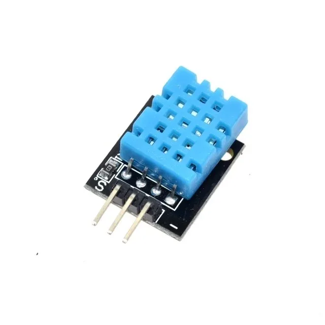
DHT11 Digital Relative Humidity and Temperature Sensor Module
Perfect sensor for multi-node weather display networks. Pair with an Arduino slave node and OLED to show live temperature and humidity readings on each display.

DHT20 SIP Packaged Temperature and Humidity Sensor
The DHT20 communicates natively over I2C — making it a natural companion for I2C OLED display nodes. More accurate than DHT11 and shares the same bus.

BMP280 Barometric Pressure and Altitude Sensor I2C/SPI Module
Add altitude and pressure readings to your OLED display network. The BMP280 is fully I2C compatible and works on the same bus as your SSD1306 OLED on each slave node.

20A Range Current Sensor Module ACS712
Monitor current draw at each node and display it on local OLEDs. The ACS712 provides analog output that any slave Arduino can read and push to its display.
Troubleshooting I2C OLED Issues
Here are the most common problems and their fixes:
| Problem | Likely Cause | Fix |
|---|---|---|
| OLED shows nothing | Wrong I2C address | Run I2C scanner sketch to find actual address (0x3C or 0x3D) |
| Slave not responding | Missing common GND | Connect all GNDs together — critical for I2C |
| Garbage on display | No pull-up resistors or duplicate pull-ups | Use exactly one pair of 4.7kΩ pull-ups on the bus |
| Intermittent data loss | Bus speed too high or wires too long | Drop to 100 kHz: Wire.setClock(100000) |
| Slave locked up after upload | I2C bus held in stuck state | Power cycle all boards to reset bus state |
Recommended Components from Zbotic

CJMCU-219 INA219 I2C Bi-directional Current/Power Monitoring Module
This I2C power monitor is an excellent addition to any OLED display node for real-time power consumption tracking. Shares the I2C bus cleanly with your OLED.
Frequently Asked Questions
Can I connect more than 2 OLEDs to one Arduino over I2C?
Standard SSD1306 OLEDs only support two I2C addresses (0x3C and 0x3D), so a maximum of two OLEDs can share one hardware I2C bus. For more displays, use an I2C multiplexer (TCA9548A) or connect each OLED to its own slave Arduino as described in this guide.
How many slave Arduinos can the master control?
The I2C protocol supports up to 127 devices on a bus (7-bit addressing). In practice, with Arduino Wire library, 10–15 slave Arduinos is a comfortable limit before bus capacitance and cable length become issues. For more nodes, consider using RS-485 for the inter-Arduino link and keeping I2C only for local peripherals.
Why is my slave Arduino freezing when used as both I2C slave and OLED driver?
This happens because Adafruit_SSD1306’s display.display() call uses the hardware Wire bus in master mode, which conflicts with the Arduino’s slave role. The fix is to use a software I2C library (SoftWire or SlowSoftWire) for the OLED, keeping hardware Wire dedicated to the inter-Arduino slave role.
Do I need separate power supplies for each Arduino?
Not necessarily. Arduino Nanos running at 5V can share a USB power bank or a single 5V regulated supply if total current draw is within limits (typically 500mA per USB port). For a 4-node system each running an OLED and sensors, a 2A 5V supply is recommended. Always connect all GNDs together.
Can I use ESP8266/ESP32 as master instead of Arduino Uno?
Yes, and it is actually a better choice for IoT projects. ESP32 has two hardware I2C buses (Wire and Wire1) and can also push display data to a cloud dashboard. The slave Arduinos can still be standard Uno/Nano boards. Just ensure the 3.3V I2C lines from ESP32 are level-shifted to 5V for the Arduino slaves.
Ready to Build Your Display Network?
Zbotic stocks a wide range of display modules, Arduino boards, sensors, and communication modules — all shipped fast across India. Whether you are in Mumbai, Bengaluru, Delhi, or Hyderabad, your components arrive quickly so your project does not stall.


Add comment