
A failing capacitor is one of the most common causes of circuit board failures — from crashing power supplies to glitchy amplifiers to unreliable microcontroller resets. The good news is that learning how to test a capacitor with a multimeter takes only a few minutes, and it can save you hours of head-scratching troubleshooting. Whether you’re diagnosing a faulty laptop motherboard, repairing an audio amplifier, or verifying components before installing them in a new project, this guide covers everything you need.
What You Will Need
- A digital multimeter (DMM) — ideally with a capacitance measurement mode (µF/nF)
- Alternatively, any multimeter with resistance (Ω) mode works for a basic check
- The capacitor you want to test, ideally removed from the circuit
- A discharge resistor (1 kΩ to 100 kΩ) for large electrolytic caps — safety measure
- Optional: dedicated ESR meter for electrolytic capacitor health checks
Safety First: Discharge the Capacitor
WARNING: Large electrolytic capacitors (especially those from power supplies, inverters, or motor drives) can hold lethal voltages even after the circuit is powered off. A 400 V, 1000 µF capacitor stores enough energy to cause a serious electric shock or explosive arcing. ALWAYS discharge capacitors before testing.
How to Safely Discharge a Capacitor
- Power off the circuit and unplug from mains.
- For small capacitors (under 100 µF, under 50 V): touch both leads briefly together with an insulated screwdriver handle, or connect a 10 kΩ resistor across the terminals for a few seconds.
- For large capacitors (over 100 µF or over 50 V): connect a 1 kΩ resistor in series with a 10W or higher resistor across the terminals. Leave connected for 30–60 seconds. Do not short large caps directly — the spark will damage the plates.
- Verify with your multimeter in DC voltage mode — measure across the capacitor and confirm it reads near 0 V before touching it.
Method 1: Measuring Capacitance Directly
If your multimeter has a capacitance mode (usually marked with the capacitor symbol or the µF/nF unit), this is the most straightforward and accurate method.
Step-by-Step
- Remove the capacitor from the circuit (in-circuit measurements are unreliable — parallel components affect the reading).
- Discharge the capacitor completely as described above.
- Read the capacitor’s rated value from its markings (e.g. 100 µF, 16 V or a 3-digit code on ceramic caps — see below).
- Set your multimeter to capacitance mode. Select a range slightly above the expected value if your meter has manual ranging.
- Connect the probes: For electrolytic (polarised) capacitors, red probe to positive (longer lead or marked with +), black probe to negative. For non-polarised caps, polarity doesn’t matter.
- Read the value. Most meters take 2–5 seconds to stabilise on a large cap.
What Is an Acceptable Capacitance Reading?
Capacitors have a tolerance specification — typically ±20% for electrolytics, ±10% for film capacitors, and ±5–10% for higher-grade ceramics. As a general rule:
- Good: Within ±20% of rated value (e.g. 100 µF cap reads 82–120 µF)
- Degraded: 20–50% below rated value — capacitor is aging, consider replacement
- Failed: Reads 0 or near-zero, or massively higher than rated value

0.1/100nF Multilayer Ceramic Capacitor (Pack of 50)
Stock up on quality 100nF capacitors — essential for decoupling and filter circuits. Easy to test with the capacitance method above.
Reading Capacitor Markings
Electrolytic capacitors are usually clearly labelled (e.g. 1000 µF, 25 V). Ceramic capacitors use a 3-digit code:
- First two digits: significant digits
- Third digit: multiplier (number of zeros to add) in picofarads
- Examples: 104 = 10 × 10⁴ pF = 100,000 pF = 100 nF = 0.1 µF; 472 = 47 × 10² pF = 4,700 pF = 4.7 nF; 221 = 22 × 10¹ = 220 pF
Method 2: Resistance/Ohm Test
If your multimeter does not have a capacitance mode, you can use the resistance (Ω) or continuity mode to check if a capacitor is short-circuited or open — though you cannot measure the actual capacitance value this way.
Step-by-Step
- Discharge the capacitor completely.
- Set the multimeter to the highest resistance range (e.g. 2 MΩ or 20 MΩ).
- Connect the probes: red to positive, black to negative for electrolytic caps.
- Watch what happens:
What to Expect for a GOOD Capacitor
When you first connect the probes, the reading starts low (the meter charges the capacitor through its internal battery) and then rises steadily toward a high resistance value (hundreds of kΩ to several MΩ). This rising behaviour is the signature of a charging capacitor — it confirms the cap is not short-circuited and has significant capacitance.
Once fully charged, a good capacitor reads OL (overload = very high resistance) — meaning no DC leakage through the dielectric.
What to Expect for a FAILED Capacitor
- Reads 0 Ω (short circuit): The capacitor is internally shorted — dielectric breakdown. Replace immediately.
- Reads OL instantly with no rise: Either the capacitor is very small (below ~1 µF — too small for the meter to show a charging curve) OR the capacitor is open-circuited (no capacitance at all).
- Rises but settles to a low value (e.g. 10 kΩ): The capacitor has excessive leakage through the dielectric — it is degraded and should be replaced in precision circuits.
Note: This method works well for electrolytic capacitors 10 µF and larger. For small capacitors (under 1 µF), the charging time is too fast to observe. Use capacitance mode or a dedicated meter.
Method 3: Voltage Charge Test
For large capacitors, the voltage test gives a strong indication of whether the cap can hold a charge — the key function of any capacitor.
- Charge the capacitor by connecting it to a DC voltage source (through a 1 kΩ current-limiting resistor) for a few seconds. Use a voltage well below the capacitor’s rated voltage.
- Disconnect the power source.
- Immediately measure the voltage across the capacitor with your multimeter in DC voltage mode.
- Note the initial voltage reading, then watch: a good capacitor holds the voltage for several seconds to minutes.
- If the voltage drops to near-zero in less than 1–2 seconds, the capacitor has high internal leakage and is failing.

0.1µF Ceramic Capacitor (Pack of 50)
High-quality ceramic capacitors ideal for bypass and filter applications — test them with the capacitance method for accurate verification.
Method 4: ESR Testing
ESR (Equivalent Series Resistance) is the internal resistance of a capacitor. For electrolytic capacitors, ESR is a critical health indicator — it typically increases as the capacitor ages or is exposed to heat. A capacitor can read its correct capacitance value but still fail in a circuit because its ESR has increased, causing it to dissipate too much power and fail to filter effectively.
Why ESR Matters
- A new 1000 µF/16 V electrolytic might have ESR of 0.1–0.3 Ω
- An aging capacitor of the same spec might measure 5–20 Ω ESR
- In a switching power supply, high ESR means the capacitor heats up, ripple voltage increases, efficiency drops, and components may fail
How to Measure ESR
Most standard multimeters do NOT measure ESR. You need either:
- A dedicated ESR meter
- An LCR meter (measures inductance, capacitance, and resistance at a test frequency)
- A component tester like the LCR-T4 (shows ESR on the LCD)
As a rule of thumb: if the capacitance is within spec but the circuit still behaves incorrectly (power supply whine, voltage ripple, amplifier instability), ESR is the likely culprit. Replace suspect electrolytic capacitors on boards that are over 5–8 years old.
Interpreting Your Readings
| Reading | What It Means | Action |
|---|---|---|
| Capacitance within ±20% of rated | Good capacitor | Use it |
| Capacitance 20–50% low | Aging/degraded | Replace in precision/critical circuits |
| Capacitance reads 0 or very near 0 | Open circuit / dead cap | Replace immediately |
| Resistance reads 0 Ω | Short circuit (dielectric breakdown) | Replace immediately |
| Resistance low but not 0 (leaky) | Partial dielectric leakage | Replace in precision circuits |
| Correct capacitance but high ESR | Internal degradation | Replace — especially in PSU/audio |
Testing Electrolytic Capacitors
Electrolytic capacitors are polarised (have a + and − terminal) and use a liquid or gel electrolyte, which dries out over time or under heat. They are the most common failing capacitor type on PCBs.
Key Points for Electrolytic Testing
- Always observe polarity when connecting probes in capacitance mode
- If the capacitor reads lower than rated, also check ESR — often the combination of low capacitance + high ESR confirms replacement
- A good electrolytic has a dielectric absorption effect — after you discharge it, a small residual voltage (tens of millivolts) will appear minutes later. This is normal and does NOT indicate leakage
- If you reverse-bias a polarised capacitor during testing, you can damage it — always observe polarity
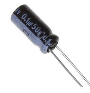
0.1µF 50V Capacitor (Pack of 50)
Reliable 50V rated capacitors — verify them with the direct capacitance method before use in your build.
Testing Ceramic Capacitors
Ceramic capacitors are non-polarised, very small, and rarely fail outright. When they do fail, it is almost always a short circuit (physical crack causing the dielectric to conduct). Ceramic caps do not suffer from electrolyte drying.
Testing Ceramic Caps
- For values 1 nF and above: use capacitance mode to verify value
- For small values (below 100 pF): most hobby multimeters cannot accurately measure these. Use an LCR meter.
- Use resistance mode to check for shorts: a good ceramic cap should read OL in both directions
- A cracked ceramic cap often shows 0 Ω resistance — this is the most common failure mode, usually from physical stress during soldering or board bending
X5R vs X7R Ceramic Capacitors and Capacitance Drift
High-value ceramic capacitors (1 µF and above) using X5R or X7R dielectrics lose capacitance under DC bias voltage — a phenomenon called DC bias derating. A 10 µF 6.3 V X5R cap under 5 V bias might read only 3–4 µF. This is normal for the dielectric type and does not indicate a faulty cap. Use Y5V caps with extra caution — they can lose 70–80% of capacitance at rated voltage.
Testing Film and Tantalum Capacitors
Film Capacitors
Polyester, polypropylene, and other film capacitors are very stable and rarely fail unless physically damaged or subjected to overvoltage. Test them the same way as ceramics — capacitance mode for value, resistance mode for shorts.
Tantalum Capacitors
Test like electrolytics — they are polarised and have a rated voltage. The critical failure mode is shorted dielectric — and unlike electrolytics, tantalum shorts can be catastrophic (fire/explosion). Always check for short circuit before powering a circuit with tantalum caps. A 0 Ω reading between the terminals means replace immediately.
In-Circuit Capacitor Testing
In-circuit testing is unreliable for most methods because parallel resistors and other components affect readings. However:
- Short-circuit check: A 0 Ω reading in-circuit is still meaningful — a shorted cap will read near-zero regardless of what’s in parallel.
- ESR meters can test in-circuit: Because they measure at a high AC frequency where other components’ impedance is high, ESR meters are relatively accurate in-circuit. This is why ESR meters are beloved by TV and monitor repair technicians.
- For capacitance measurement, always desolder at least one lead before testing for an accurate result.
Visual Inspection: Spotting Bad Caps
Before grabbing your multimeter, check for these visual clues:
Signs of a Failed Electrolytic Capacitor
- Bulging top: The top vent of the capacitor (designed to release pressure) is visibly domed upward. This is a classic sign of internal gas buildup from electrolyte breakdown. The cap is dead.
- Leaked electrolyte: Brown or black residue around the base of the capacitor or on the PCB. The electrolyte has leaked out — the capacitor has zero remaining capacitance.
- Burnt smell or discolouration: Carbon residue or discolouration indicates thermal stress.
- Exploded vent: The top cross-vent is pushed open or the entire top has cracked — catastrophic internal pressure release.
Signs of a Failed Ceramic or Film Capacitor
- Physical cracks: Hairline cracks in the body, especially near the leads. These cause intermittent short circuits.
- Burn marks: Black or brown discolouration from overvoltage.
- Missing lead or pad: Lead snapped off or lifted PCB pad from mechanical stress.
Frequently Asked Questions
Can I test a capacitor without a multimeter?
You can do a basic charge-hold test with a LED and battery: charge the cap from the battery (with a 1 kΩ series resistor), then disconnect the battery and connect the LED in series with the cap. A good cap will briefly light the LED as it discharges through it. A shorted cap won’t light the LED (instantly discharged), and an open cap won’t either. This is a rough functional test only.
My multimeter reads higher capacitance than the rated value. Is the cap bad?
Not necessarily. Electrolytics typically have ±20% tolerance, so reading slightly over rated is within spec. However, if the reading is more than 50% over rated, the cap may have been reverse-biased at some point (polarity applied wrong), which can increase apparent capacitance temporarily — but the cap is degraded. If in doubt, replace it.
How do I test a capacitor that is soldered on a PCB?
For an accurate capacitance reading, desolder at least one lead. For a quick short-circuit check, measure resistance between the two leads in-circuit with power off and cap discharged — if it reads near zero, it’s shorted. For ESR, use an ESR meter which works in-circuit.
What causes a capacitor to fail?
Main causes: overvoltage (exceeding rated voltage), reverse polarity (for electrolytic/tantalum), overheating (proximity to hot components, poor PCB ventilation), age/hours in service (electrolyte drying in electrolytics), high ripple current (excess heating from AC component in the current), and physical stress (cracked ceramics from board flexing or soldering thermal shock).
Can I use a bad capacitor in a non-critical circuit?
A capacitor with slightly low capacitance (but no short circuit and low ESR) can sometimes be used in non-critical applications like timing circuits where exact values aren’t critical. However, a shorted or leaky capacitor should never be used — it will affect the circuit and may damage other components.
My multimeter’s capacitance mode reads 0.1 µF as just “1” or shows nothing. Why?
Your meter may be on the wrong range. Set it to the range just above the expected capacitance. If it reads “1” (just the digit 1 on the left), it means overrange — switch to a higher range. Also verify the cap is discharged before measuring — a partially charged cap can give wrong readings or even damage the meter’s input circuit.
Need replacement capacitors? Zbotic.in stocks ceramic capacitors in popular values — 100nF, 0.1µF, and more — in convenient packs. Shop at zbotic.in for fast delivery across India and keep your component stock fresh.


Add comment