
Introduction
When it comes to power electronics, one component stands at the very heart of almost every circuit: the transformer. Understanding transformer types in electronics — step-up, step-down, isolation, centre-tap, and auto-transformers — is essential for anyone designing power supplies, audio amplifiers, or industrial control circuits. In India, where mains voltage is 230V AC at 50 Hz, selecting the right transformer type can mean the difference between a reliable design and a burnt circuit. This comprehensive guide explains every major type, how they work, when to use each, and how to calculate the turns ratio for your specific project.
Table of Contents
- How Transformers Work: The Basics
- Step-Down Transformer: The Workhorse of Electronics
- Step-Up Transformer: Boosting Voltage
- Isolation Transformer: Safety First
- Centre-Tap Transformer: For Rectifier Circuits
- Auto-Transformer: Compact and Efficient
- How to Select the Right Transformer for Your Project
- Frequently Asked Questions
How Transformers Work: The Basics
A transformer works on the principle of electromagnetic induction, discovered by Michael Faraday in 1831. When alternating current flows through the primary winding, it creates a time-varying magnetic flux in the iron core. This changing flux induces a voltage in the secondary winding. The relationship between the primary and secondary voltages is determined by the turns ratio:
Vprimary / Vsecondary = Nprimary / Nsecondary = Turns Ratio (n)
Similarly, because power must be conserved (ignoring losses), the current relationship is the inverse:
Iprimary / Isecondary = Nsecondary / Nprimary = 1/n
An ideal transformer is 100% efficient — all power transferred from primary to secondary. Real transformers have losses due to winding resistance (copper losses) and magnetic core losses (iron losses, hysteresis, and eddy currents). Modern EI-core and toroidal transformers achieve 90–98% efficiency at full load.
Crucially, transformers only work with alternating current — not DC. If you connect a DC source to a transformer primary, the magnetic field will not change, no voltage will be induced in the secondary, and the primary winding may overheat and burn out (since only its resistance limits the current, not inductive reactance).
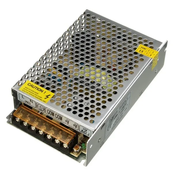
12V 10A SMPS – 120W DC Metal Power Supply
A modern switched-mode power supply that uses a high-frequency transformer internally, offering regulated 12V DC at 10A from 230V mains — much lighter than a linear transformer supply of the same rating.
Step-Down Transformer: The Workhorse of Electronics
A step-down transformer reduces voltage from a higher level to a lower level. It has more turns on the primary than the secondary (n > 1). This is by far the most common transformer type in electronics, found in virtually every mains-powered device from chargers to amplifiers.
Working Example
You need 12V AC from 230V mains. The turns ratio needed is 230/12 ≈ 19.2:1. So for every 19.2 turns on the primary, the secondary needs 1 turn. If the primary has 1920 turns, the secondary will have 100 turns. For a 1A load at 12V (12W), the primary draws only 12W/230V ≈ 52mA.
Power Rating in VA
Transformers are rated in Volt-Amperes (VA), not Watts, because the load may be reactive. Common step-down transformer ratings for Indian hobbyists:
- 500mA at 9V → use a 9VA or larger transformer
- 1A at 12V → use a 15VA or 20VA transformer (allow 25–50% headroom)
- 2A at 12V → use a 30VA transformer
- 5A at 12V → use a 75VA or 100VA transformer
Common Secondary Voltages Available in India
6V, 9V, 12V, 15V, 18V, 24V — all readily available. Remember: these are RMS values. The peak DC voltage after a bridge rectifier and capacitor filter will be approximately 1.414 × Vsecondary – 1.4V.
Core Types
- EI-core (laminated): Most common, low cost, rectangular shape, moderate efficiency
- Toroidal: Donut-shaped, higher efficiency, lower electromagnetic interference (EMI), more expensive. Preferred for audio equipment and sensitive analog circuits.
- C-core (UI-core): Used in high-power industrial transformers
Step-Up Transformer: Boosting Voltage
A step-up transformer increases voltage from a lower level to a higher level. The secondary has more turns than the primary (n < 1 from secondary perspective). While less common in everyday electronics (most circuits need lower voltages), step-up transformers are used in specific applications.
Applications
- High-voltage power supplies: CRT monitors, tube amplifiers (valves need 200–400V DC), Geiger counters, plasma displays
- Neon sign transformers: 230V input → 2000–15000V output
- Tesla coils: High-voltage, high-frequency experiments
- Power transmission: Power plants step up 11kV to 220kV or 400kV for long-distance transmission (though this is not an electronics-scale example)
- Inverter output stage: Some off-grid inverters in India step up 12V battery to 230V AC using a high-frequency SMPS transformer
Safety Note for Indian Makers
Step-up transformers producing voltages above 50V AC or 120V DC are considered hazardous. Always use proper insulation, enclosed enclosures with clear warning labels, and never touch the output terminals of a high-voltage step-up transformer without discharging any capacitors first. High-voltage capacitors can retain lethal charge long after power is removed.
Isolation Transformer: Safety First
An isolation transformer has a 1:1 turns ratio — the primary and secondary voltages are equal. Its purpose is not to change voltage but to provide galvanic isolation — breaking the direct electrical connection between the primary and secondary circuits.
Why Isolation Matters
In India, the mains supply (230V, 50Hz) has one conductor at line (phase) voltage and one at neutral (close to earth potential). Many older electronic devices have one side of their circuit connected to the mains line. If you touch such a circuit without isolation, you complete the circuit through your body to earth — a potentially fatal shock.
An isolation transformer’s secondary floats at no defined potential relative to earth — neither terminal is grounded. This greatly reduces (though does not eliminate) the risk of electric shock when working on the circuit, since you need to touch both output terminals simultaneously to receive a shock.
Applications
- Lab safety when servicing mains-powered equipment (TVs, UPS, inverters)
- Medical equipment — patient isolation (IEC 60601 requires isolation in patient-connected circuits)
- Reducing ground loops in audio systems (1:1 audio isolation transformers in the signal path)
- Switch-mode power supplies (the switching transformer provides inherent isolation)
- Industrial fieldbus interfaces (RS-485, CAN bus isolation for noise immunity)

1.2M AC 10A 250V Power Cord Cable
A quality AC power cord for connecting your bench power supply, isolation transformer, or SMPS to the mains safely. Rated for 10A and 250V.
Centre-Tap Transformer: For Rectifier Circuits
A centre-tap transformer is a step-down transformer with an additional wire connected to the exact midpoint of the secondary winding. This creates two equal secondary windings in series, each with half the total secondary voltage.
How It Is Used
In a centre-tap full-wave rectifier, the centre tap becomes the DC negative (0V reference), and each end of the secondary feeds one of the two rectifier diodes. This allows full-wave rectification with only two diodes instead of four. The result is lower diode voltage drop (only one diode in series instead of two) and slightly higher output voltage.
Example
A 12V-0-12V centre-tap transformer has 12V RMS on each half. After a full-wave centre-tap rectifier, the peak output is 12V × 1.414 – 0.7V ≈ 16.3V. After filtering, you get approximately 15–16V unregulated DC, regulated to 12V with a 7812 regulator.
Limitation
The centre-tap approach requires each diode to handle a PIV (Peak Inverse Voltage) of 2Vm — twice the peak voltage — compared to just Vm for a bridge rectifier. This means you need higher-rated diodes, which offsets some of the cost saving from using fewer diodes. Centre-tap transformers are also more expensive than plain secondary transformers.
Auto-Transformer: Compact and Efficient
An auto-transformer uses a single winding with a tapped connection, where the primary and secondary windings share part of the same winding. This makes it physically smaller and more efficient than a conventional two-winding transformer for the same power rating — but it provides no galvanic isolation.
Variac (Variable Auto-Transformer)
The most common auto-transformer that Indian electronics enthusiasts encounter is the Variac (or powerstat), a variable auto-transformer. It uses a sliding contact (brush) that can move along the winding to pick off any fraction of the mains voltage. This gives a continuously variable AC output from 0V to 270V (or even beyond the input) from a 230V mains supply. Variacs are widely used in electronics labs for testing equipment at different supply voltages and for gradually bringing up a circuit under test (called “ramping up”).
Limitations
- No isolation — dangerous for live circuit servicing
- Output is not electrically isolated from mains — ground loops possible in audio applications
- Cannot step up voltage by more than the total winding (though some designs allow 130% of input)
How to Select the Right Transformer for Your Project
Follow this step-by-step process when choosing a transformer for your next electronics project in India:
- Determine required DC output voltage: Add 15–20% to account for rectifier diode drops and regulation losses. If you need 12V regulated DC, your unregulated DC needs to be at least 14–15V, which means a 10–12V AC secondary after rectification.
- Calculate required VA rating: VA = Output DC Voltage × Maximum Load Current. Add 25–50% headroom. For a 1A load at 12V, you need at least 15–18VA transformer.
- Choose secondary voltage: Select the nearest standard value: 6V, 9V, 12V, 15V, 18V, 24V.
- Decide on isolation requirement: If safety is critical (medical, lab work on mains equipment), use a two-winding transformer — never an auto-transformer. If you are stepping down from 230V to low voltage for a hobby project, any standard step-down transformer with a two-winding design provides isolation.
- Choose core type: EI-core for cost-sensitive projects, toroidal for audio or sensitive analog work.
- Check local availability: Standard transformers (230V primary, 9V/12V/15V secondary, 500mA–5A) are readily available from electronics suppliers across India for ₹80–₹500 depending on VA rating.
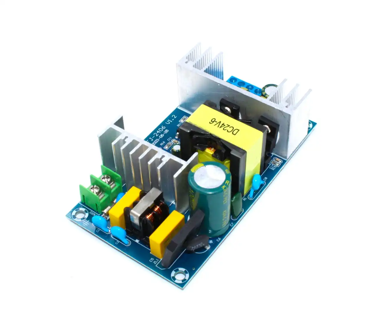
150W AC-DC Buck Converter 100V-240V to 24V
A compact SMPS module that converts 230V AC mains to regulated 24V DC at up to 9A — equivalent to a heavy traditional step-down transformer, in a fraction of the size and weight.

12V 2A Power Supply with DC Plug Adapter
Regulated 12V 2A DC adapter with standard 5.5mm barrel plug — perfect for powering your electronics projects and prototypes without building a power supply from scratch.
Frequently Asked Questions
Q1: What is the difference between a step-up and step-down transformer?
A step-up transformer has more turns on the secondary than the primary, so it increases voltage (and decreases current proportionally). A step-down transformer has fewer turns on the secondary, so it decreases voltage (and increases current). The power transferred is the same in both cases (minus losses).
Q2: Can I use a transformer to convert 230V to 110V for US appliances in India?
Yes — a step-down transformer with a 230V primary and 110V secondary at the appropriate VA rating works perfectly. For a 100W US appliance, use at least a 150VA transformer. Many such converters are available at electronics shops across India for ₹300–₹1500 depending on power rating.
Q3: Why is transformer VA rating not the same as Watts?
VA (Volt-Amperes) is apparent power, while Watts is real power. The ratio is the power factor. For purely resistive loads (heaters, incandescent bulbs), VA = Watts (power factor = 1). For reactive loads (motors, capacitive power supplies), the power factor is less than 1, and you need more VA than Watts. Transformers are rated in VA because they must handle the full current regardless of the phase relationship — copper losses depend on current squared, not power factor.
Q4: Is an SMPS transformer the same as a mains transformer?
No. An SMPS (Switch-Mode Power Supply) transformer operates at much higher frequencies (20kHz–500kHz) than a mains transformer (50 Hz in India). Because core losses and size are inversely proportional to frequency, SMPS transformers can be dramatically smaller and lighter for the same power rating. SMPS transformers use ferrite cores instead of the silicon steel laminations used in mains-frequency transformers.
Q5: How do I know if a transformer is overloaded?
Signs of transformer overload include: excessive heat (more than slightly warm to touch), humming louder than usual, the secondary voltage dropping significantly under load, and in severe cases, a burning smell. Always size your transformer with at least 25% headroom above your expected maximum load current to prevent overloading and extend transformer life.
Conclusion
Transformer types in electronics cover a wide range of applications — from the humble 12V step-down transformer in your first power supply to the high-voltage step-up in a tube amplifier, or the safety-critical isolation transformer on a service bench. Understanding the turns ratio, VA rating, core type, and isolation requirements will help you make the right choice every time.
Ready to power your next project? Zbotic carries regulated DC power supplies, SMPS modules, and all the passive components you need for power supply design. Visit our Electronics Components & Basics store and start building today!


Add comment