
H-Bridge Motor Driver Circuit: Build with MOSFETs Guide
An H-bridge motor driver MOSFET circuit build guide is one of the most searched topics among Indian robotics enthusiasts — and for good reason. The H-bridge is the fundamental building block for controlling DC motors in both directions, and building one yourself with MOSFETs teaches you power electronics, gate driving, and motor control all at once. Whether you are building a robot car, a motorised camera slider, or an automated window blind, this guide walks you through the complete design from theory to working circuit.
What Is an H-Bridge and Why Use MOSFETs?
An H-bridge is a switching circuit that allows a DC motor to be driven in either direction by reversing the polarity of voltage applied to it. The name comes from the visual resemblance of the circuit to the letter “H” — the motor sits on the crossbar, with two switches on each side forming the legs.
You could build an H-bridge using bipolar transistors (BJTs), relays, or integrated circuits like the L298N. So why use MOSFETs?
- Higher efficiency: MOSFETs have very low on-resistance (R_DS(on)) — often under 10 mΩ — meaning they waste very little power as heat compared to BJTs.
- Faster switching: MOSFETs switch in nanoseconds, enabling PWM frequencies up to hundreds of kHz for smooth motor speed control.
- Voltage-controlled: MOSFETs are voltage-driven (not current-driven like BJTs), so gate drive circuitry is simpler and draws minimal current.
- Higher current capacity: A single N-channel MOSFET like the IRFZ44N can handle 49 A continuous — far beyond most BJT equivalents in the same package size.
How an H-Bridge Works: Forward, Reverse, Brake, Coast
Label the four switches Q1 (top-left), Q2 (bottom-left), Q3 (top-right), Q4 (bottom-right). The motor connects between the two midpoints.
| Mode | Q1 | Q2 | Q3 | Q4 |
|---|---|---|---|---|
| Forward | ON | OFF | OFF | ON |
| Reverse | OFF | ON | ON | OFF |
| Brake | OFF | ON | OFF | ON |
| Coast | OFF | OFF | OFF | OFF |
Critical rule: Never turn on Q1 and Q2 simultaneously (or Q3 and Q4). This creates a shoot-through condition — a direct short from supply to ground that will destroy your MOSFETs instantly. Always implement a dead-time delay (typically 100–500 ns) between turning one switch off and the other on.
Choosing the Right MOSFETs for Your Motor
The most common beginner mistake is picking the wrong MOSFET. Here is what to check:
For the High Side (Top Switches) — P-Channel or Bootstrapped N-Channel
Pure MOSFET H-bridges use P-channel MOSFETs for the high-side switches (Q1, Q3) and N-channel for the low side (Q2, Q4). This simplifies gate driving since N-channel gates are driven with a voltage above GND, while P-channel gates are driven below V+.
For small motors (under 2 A), popular choices:
- High side (P-ch): IRF9540 (rated 23 A, V_DS = −100 V, R_DS(on) = 0.117 Ω)
- Low side (N-ch): IRFZ44N (rated 49 A, V_DS = 55 V, R_DS(on) = 0.0175 Ω)
- Small motor (both N-ch with bootstrap driver): 2N7000 or AO3400 for currents under 300 mA
Key Ratings to Check
- V_DS: Must be greater than your supply voltage with margin (use 2× margin minimum)
- I_D: Continuous drain current — must exceed peak motor stall current
- V_GS(th): Gate threshold — must be compatible with your logic level (3.3 V or 5 V)
- R_DS(on): Lower is better — determines heat dissipation at operating current
Complete H-Bridge Schematic and Component List
Here is a basic dual-voltage H-bridge using complementary MOSFET pairs, suitable for 12 V motors up to 3 A:
Component List
- Q1, Q3: IRF9540 P-channel MOSFET (TO-220) × 2
- Q2, Q4: IRFZ44N N-channel MOSFET (TO-220) × 2
- D1–D4: 1N4007 or Schottky diode (1N5819) — flyback protection × 4
- R1–R4: 10 kΩ gate resistors × 4
- R5, R6: 100 kΩ pull-down resistors for N-channel gates × 2
- R7, R8: 10 kΩ pull-up resistors for P-channel gates × 2
- C1: 100 µF electrolytic decoupling capacitor (across supply)
- C2: 100 nF ceramic decoupling capacitor (across supply)
- Motor: 12 V DC brushed motor
- Power supply: 12 V SMPS
Gate Drive Logic
For forward rotation: Drive IN1 HIGH (5V) → Q2 turns ON (N-ch, gate pulled high); simultaneously drive IN2 LOW → Q3 turns ON (P-ch, gate pulled low). Current flows: 12V → Q3 → Motor → Q2 → GND.
For Arduino 5V control of P-channel gates directly: since V_GS(th) for IRF9540 is −4 V, a 5V Arduino driving the gate through a 10 kΩ resistor (gate pulled to 12V via pull-up) means: V_GS = 5 − 12 = −7 V — sufficient to turn on the P-channel. This works without additional level shifting for 12 V supplies.
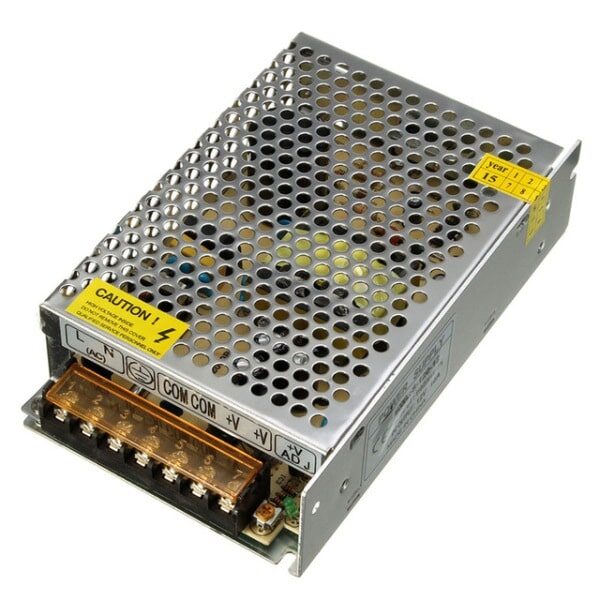
12V 10A SMPS – 120W DC Metal Power Supply
A stable 12 V supply is essential for H-bridge motor driver testing. This 120 W SMPS handles motors up to 10 A, with metal casing for heat dissipation.
Step-by-Step Circuit Build on Breadboard
For prototyping and learning, use a full-size 830-point breadboard. For currents above 1 A, solder on a PCB — breadboard contacts can’t handle sustained high currents reliably.
Step 1: Power rails
Connect 12 V to the top power rail (+) and GND to the bottom rail (−). Add a 100 µF capacitor across the rails close to where the motor connects, and a 100 nF ceramic capacitor in parallel for high-frequency decoupling.
Step 2: Place MOSFETs
Place Q1 (IRF9540) with source to 12 V rail, drain pointing down. Place Q2 (IRFZ44N) with source to GND, drain pointing up. Connect Q1 drain to Q2 drain — this is Motor Terminal A. Repeat for Q3/Q4 — this is Motor Terminal B.
Step 3: Gate resistors
Add 10 kΩ resistors from each gate to the control input line. These limit gate charge current and reduce switching noise (slows switching slightly, which can actually help reduce EMI).
Step 4: Pull resistors
N-channel gates: add 100 kΩ from gate to GND (ensures MOSFET is OFF when control input is floating). P-channel gates: add 10 kΩ from gate to 12V (ensures P-ch is OFF when control input floats).
Step 5: Flyback diodes
Place 1N5819 Schottky diodes across each MOSFET (anode to source, cathode to drain for N-ch; reversed for P-ch). These protect against voltage spikes when the motor coil discharges.
Step 6: Connect motor
Connect motor terminals between Terminal A and Terminal B. Use M-F jumper wires to connect control inputs to Arduino digital pins.

10CM Male To Female Breadboard Jumper Wires 2.54MM – 40Pcs
Connect Arduino digital pins to your H-bridge circuit with these M-F jumper wires. Flexible, colour-coded, and perfect for quick circuit changes during testing.
Controlling H-Bridge with Arduino and PWM
With the hardware ready, here is the Arduino code for complete motor control:
// H-Bridge Motor Control
// IN1 = Q1/Q2 control, IN2 = Q3/Q4 control
const int IN1 = 9;  // PWM pin
const int IN2 = 10; // PWM pin

void setup() {
  pinMode(IN1, OUTPUT);
  pinMode(IN2, OUTPUT);
  motorStop();
}

void motorForward(int speed) {
  // speed: 0-255
  analogWrite(IN1, speed);
  digitalWrite(IN2, LOW);
}

void motorReverse(int speed) {
  digitalWrite(IN1, LOW);
  analogWrite(IN2, speed);
}

void motorBrake() {
  digitalWrite(IN1, LOW);
  digitalWrite(IN2, LOW);
}

void motorStop() {
  analogWrite(IN1, 0);
  analogWrite(IN2, 0);
}

void loop() {
  motorForward(200);  // ~78% speed forward
  delay(2000);
  motorBrake();
  delay(500);
  motorReverse(150);  // ~59% speed reverse
  delay(2000);
  motorStop();
  delay(1000);
}
PWM on the gate of an N-channel MOSFET effectively controls motor speed by rapidly switching the current on and off. At 200/255 ≈ 78% duty cycle, the motor sees an average of 12 × 0.78 = 9.4 V — allowing speed adjustment without wasting energy as heat in a series resistor.
Important Arduino Note
The Arduino 5 V GPIO is fine for driving N-channel MOSFET gates directly if V_GS(th) is under 4 V. For P-channel high-side control, you need inverting logic or a gate driver IC (like IR2104, TC4420) for clean switching at higher speeds.
Protection Circuits: Flyback Diodes and Dead Time
Flyback (Freewheeling) Diodes
Every inductive load (motor, solenoid, relay coil) generates a large voltage spike when current is suddenly interrupted — the motor’s magnetic field collapses and induces a back-EMF that can be 10× the supply voltage or more. Without flyback diodes, this spike destroys MOSFETs. Place a diode across each MOSFET, oriented to conduct during the spike (reversed biased during normal operation). Use fast-recovery Schottky diodes (1N5819, SS34) for better performance at high PWM frequencies.
Dead Time
Dead time is a mandatory short delay (100–500 ns) between turning one MOSFET off and the complementary MOSFET on. During this time, neither switch conducts. Without dead time, shoot-through occurs and the circuit fails instantly. In hardware, RC delays on gate drive lines add dead time. Gate driver ICs like IR2104 include programmable dead time internally.
Current Sensing
Add a 0.1 Ω shunt resistor in series with the low-side source pin. The voltage across it (in millivolts) = motor current × 0.1. Feed this to Arduino’s analog input for stall detection and overcurrent protection.
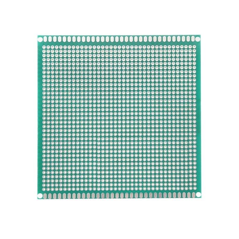
10 x 10 cm Universal PCB Prototype Board Single-Sided 2.54mm
Once you’ve tested your H-bridge on a breadboard, solder it onto this universal prototype PCB for a permanent, high-current capable motor driver build.
Heat Management
Even efficient MOSFETs dissipate heat. At 3 A with R_DS(on) = 0.1 Ω: P = I² × R_DS(on) = 9 × 0.1 = 0.9 W per MOSFET. At high duty cycles, add TO-220 heatsinks with thermal paste. For continuous loads above 5 A, forced air cooling is recommended.
Frequently Asked Questions
Q1: Can I use the L298N instead of building a discrete MOSFET H-bridge?
Yes, the L298N is an integrated H-bridge that is far easier to use for beginners. However, it has high internal losses (1.4 V drop per switch, so 2.8 V total at full current). For motors above 2 A or battery-powered robots where efficiency matters, a discrete MOSFET bridge is much better. Build the L298N first to understand H-bridge operation, then graduate to MOSFETs.
Q2: What causes my MOSFETs to get very hot?
Common causes: shoot-through (check your logic and dead time), excessive on-resistance (choose a lower R_DS(on) MOSFET), gate not fully driven (insufficient V_GS — MOSFETs in linear region), or motor stall condition drawing much higher current than rated.
Q3: How do I calculate the maximum motor current my H-bridge can handle?
The limiting factor is the lower of: MOSFET I_D rating, trace/wire current capacity, and thermal dissipation. Calculate I²R heat in the MOSFETs, add heatsinks if needed. Always test at stall current — this is when motors draw the most current, often 5–10× the running current.
Q4: Can this circuit control a stepper motor?
Two H-bridges are needed for a bipolar stepper motor (one per coil). A single H-bridge only controls one DC motor. For steppers, purpose-built driver ICs like A4988 or DRV8825 are simpler and include microstepping, current limiting, and protection in one chip.
Q5: What is the safe PWM frequency for my H-bridge?
Arduino default PWM frequency is 490 Hz (pins 5/6: 980 Hz). This is safe but audible as a buzzing sound from the motor. Higher frequencies (20+ kHz) are inaudible but require faster MOSFETs and precise dead-time control. For most hobby projects, 1–10 kHz gives a good balance.
Build your motor driver today! Source MOSFETs, resistors, prototype PCBs, and power supplies from Zbotic.in — all the components you need for this project are in stock with fast delivery across India. Join thousands of Indian makers building real circuits with quality components.


Add comment