
When engineers and makers talk about DC-DC converter efficiency in synchronous versus asynchronous buck topologies, the conversation gets surprisingly deep very quickly. At first glance, both types step down a higher DC voltage to a lower DC voltage — a task critical in everything from a ₹200 breadboard LM2596 module to a sophisticated satellite power management system. But the internal architecture is radically different, and that difference has profound effects on efficiency, heat generation, cost, and component count. Whether you are designing a solar-powered sensor node for a farm in Maharashtra, building a high-performance drone ESC in Pune, or simply trying to understand why your cheap buck module runs hot, this guide will clarify every important aspect.
How a Buck Converter Works: The Basics
A buck converter is a switch-mode power supply (SMPS) that uses a high-frequency switching element (transistor) to transfer energy from input to output in pulses, storing energy temporarily in an inductor and capacitor. Unlike a linear regulator that dissipates excess voltage as heat (P = (Vin − Vout) × I), an ideal buck converter merely redirects energy — waste only comes from real-world component losses.
The core switching cycle is:
- On phase: The high-side switch closes. Current flows from Vin through the inductor to the output capacitor and load. Inductor current ramps up.
- Off phase: The high-side switch opens. Inductor current (which cannot instantly drop to zero) must find a return path — this is where asynchronous and synchronous topologies diverge.
The duty cycle D = Vout / Vin determines how long the switch stays on per cycle. At 12 V in and 5 V out, D = 41.7%. The switching frequency typically ranges from 150 kHz to 2 MHz in modern converters.
Asynchronous (Diode-Rectified) Buck Converters
In an asynchronous buck converter, the off-phase current path is provided by a freewheeling diode — typically a Schottky diode placed between the switching node and ground. When the high-side MOSFET turns off, the inductor forces current through this diode to maintain the output voltage.
Why Schottky?
A standard silicon PN diode has a forward voltage drop of 0.6–0.7 V, which would waste significant power. Schottky diodes have lower forward drops of 0.2–0.4 V, making them preferred in power circuits. However, this drop is still non-zero — and every milliwatt lost here reduces efficiency.
Power Loss in the Diode
Diode conduction loss = Vf × IL × (1 − D). At 5 A output, 0.3 V Schottky forward voltage, and D = 0.42 (12 V to 5 V): Loss = 0.3 × 5 × 0.58 = 0.87 W continuously. On a 25 W total output (5 V × 5 A), this single loss is already 3.5% of output power — before accounting for MOSFET switching losses, inductor DCR, and gate drive losses.
Common Asynchronous ICs
The LM2596 (Vishay/TI, adjustable 1.2–37 V, 3 A, 150 kHz) is the most popular IC for DIY buck modules in India. The MC34063 and XL4016 are other common examples. All are inexpensive, widely available, easy to use with minimal external components, and typically achieve 70–85% efficiency.
Synchronous Buck Converters: The MOSFET Difference
A synchronous buck converter replaces the freewheeling diode with a second MOSFET — the low-side switch. The gate driver operates this MOSFET in synchrony with the high-side switch (hence the name): when the high-side turns off, the low-side turns on, providing a very low-resistance current path for the inductor’s flyback current.
Why MOSFETs Win Over Diodes
An N-channel MOSFET in saturation has an extremely low on-resistance (Rds_on). Modern power MOSFETs achieve Rds_on values of 1–10 milliohms. At 5 A and 5 mΩ, the conduction loss is only 0.025 × 5² = 0.125 W — versus 0.87 W for the Schottky diode in our earlier example. That is nearly a sevenfold reduction in this single loss mechanism.
Synchronous Buck Architecture Details
Critical to synchronous operation is dead time — a brief period (typically 10–100 ns) when both switches are off, preventing shoot-through (a direct short from Vin to GND through both MOSFETs). Gate driver ICs manage this automatically. During dead time, the body diode of the low-side MOSFET conducts briefly, introducing a small residual loss. However, this is far shorter-duration than the full Schottky conduction phase.
Common Synchronous Buck ICs
In the hobbyist and professional Indian market: MP2307 (4.75–23 V, 3 A, 340 kHz), LM3150 (6–42 V, 3 A), XL6009 (boost — not buck, but synchronous variants exist), and the popular MP1584 (4.5–28 V, 3 A, 1.5 MHz) found in many compact blue modules. At the professional end: TPS62135, LT8640, and MAX77827 achieve above 95% peak efficiency.
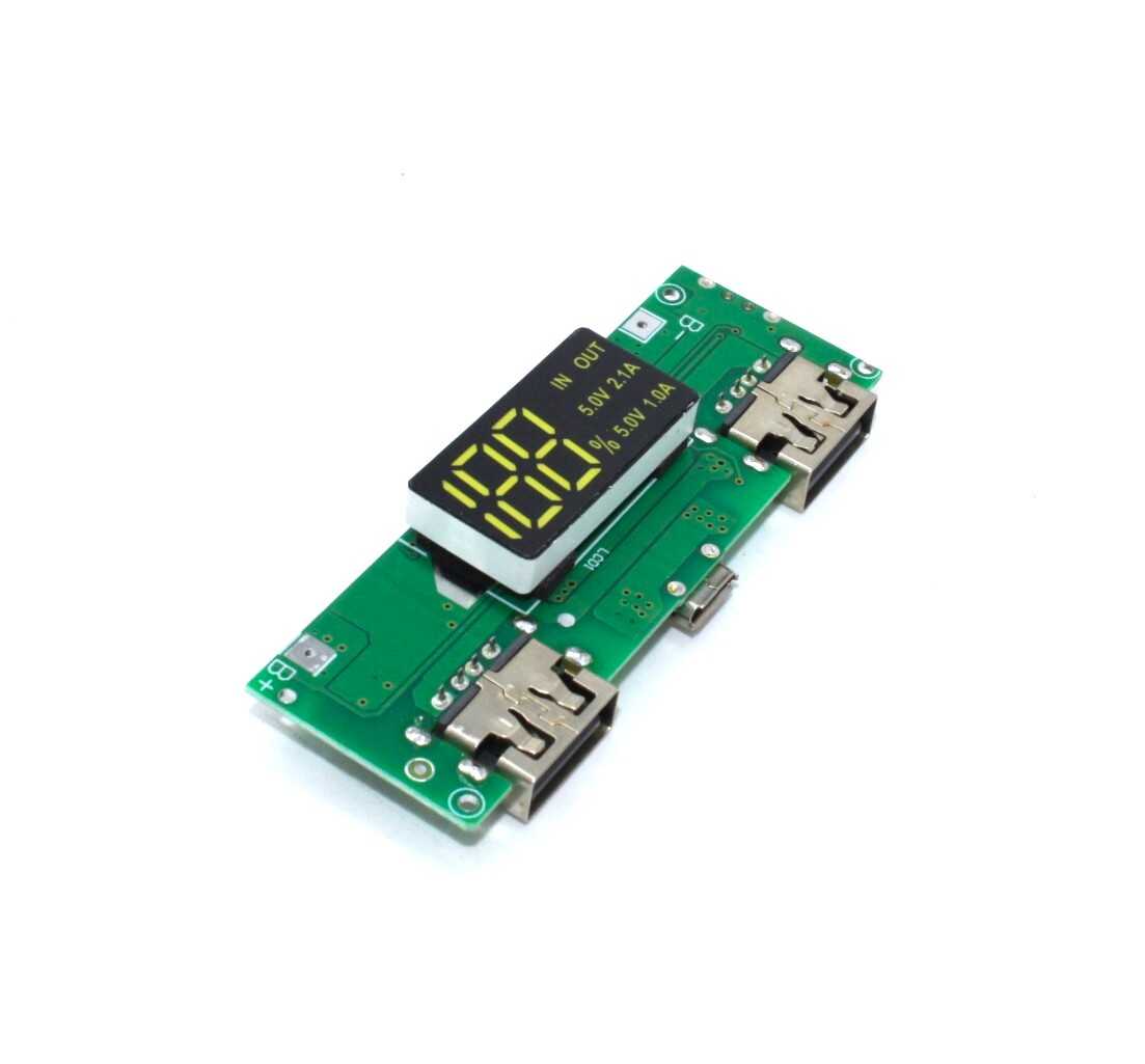
18650 5V 1A/2A Lithium Battery Boost Module with Dual USB Output
A synchronous boost (step-up DC-DC) module with high conversion efficiency, digital display, and dual USB ports. Built on a boost topology to convert 3.7 V Li-ion to regulated 5 V for powering microcontrollers and peripherals.
Efficiency Comparison: Where the Numbers Come From
Buck converter efficiency (η) = Pout / Pin = (Vout × Iout) / (Vin × Iin). Losses that reduce efficiency include:
| Loss Mechanism | Asynchronous Impact | Synchronous Impact |
|---|---|---|
| Diode / Low-Side Conduction | High (Vf × IL × (1−D)) | Very Low (IL² × Rds_on × (1−D)) |
| High-Side Switch Conduction | Medium (MOSFET Rds_on) | Medium (MOSFET Rds_on) |
| Switching Losses (CV²f) | Low (1 switch) | Higher (2 switches + gate drive) |
| Inductor DCR Loss | Identical | Identical |
| Quiescent Current | Low (simple IC) | Higher (gate driver ICs) |
| Typical Peak Efficiency | 75–88% | 88–97% |
At full load (5 A), a synchronous converter running at 93% efficiency versus an asynchronous at 83% means 2.15 W vs 5.1 W wasted as heat on a 25 W output. Over a year of continuous operation, that difference is significant — both in thermal management design and electricity cost (important for solar-powered IoT deployments in rural India).
Light Load Efficiency: An Underrated Factor
At light loads (below 10% of rated current), the picture gets more nuanced. Synchronous converters face a challenge: their low-side MOSFET body diode can allow current to flow backwards (from inductor back to Vin) if the converter stays in Continuous Conduction Mode (CCM). This reverse inductor current wastes energy.
Modern synchronous converters handle this with two techniques:
- Discontinuous Conduction Mode (DCM): The controller detects near-zero inductor current and skips switching cycles. This maintains efficiency but increases output ripple.
- Pulse Frequency Modulation (PFM) / Burst Mode: At very light loads, the converter fires a burst of pulses and then sleeps, dramatically reducing quiescent losses. Many modern ICs (TPS62135, MAX15053) automatically switch between PWM and PFM based on load. Quiescent current in PFM sleep can be as low as 6 µA — critical for battery-powered IoT nodes in standby mode.
An asynchronous converter in DCM naturally avoids reverse current (the diode blocks it) and can actually out-perform a synchronous converter in light-load efficiency due to lower quiescent current. This is why some battery-powered sensor designs intentionally use asynchronous converters for better sleep-mode efficiency.
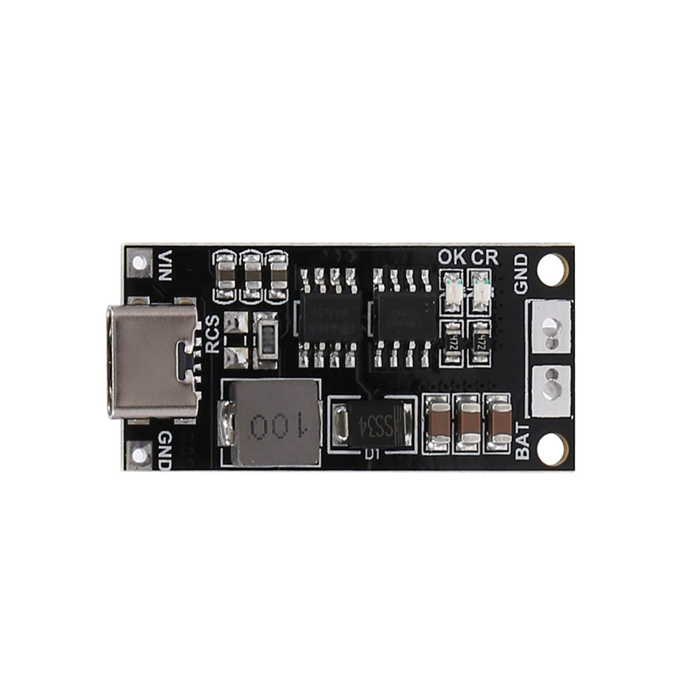
18650 Lithium Ion Charger Type-C to 3S 12.6V 2A Boost Module
A high-efficiency boost module that charges three 18650 cells in series (3S, up to 12.6V) via USB-C input at 2A. Uses synchronous boost topology for improved efficiency compared to diode-rectified alternatives.
Choosing the Right Topology for Your Project
Here is a practical decision framework for Indian makers choosing between synchronous and asynchronous buck converters:
Choose Asynchronous When:
- Cost is the primary constraint and efficiency above 85% is not required.
- Output current is below 1 A (where the absolute power loss from the diode is small in watts).
- The project has intermittent or very light loads and the converter will spend most time in DCM/sleep.
- You need simplicity and robustness — fewer active components mean fewer potential failure modes.
- Input voltage is low (below 5 V) where Schottky diodes with 0.2 V drop remain acceptable.
Choose Synchronous When:
- Output current exceeds 2 A continuously — at high currents, the efficiency difference directly translates to significant heat and energy waste.
- Battery-powered devices where maximising runtime is critical (FPV drone ESCs, portable instruments, IoT field devices).
- Thermal constraints are tight — high efficiency means less heat to dissipate, enabling smaller enclosures.
- High frequency (above 500 kHz) is needed for compact inductors and capacitors.
- Professional product design where datasheet-level efficiency specifications matter.
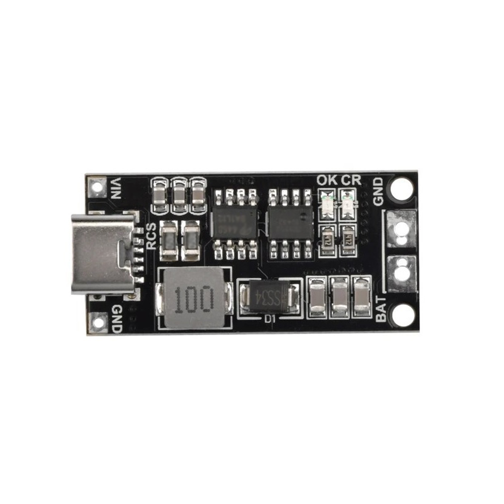
18650 Lithium Ion Charger Type-C to 3S 12.6V 4A Boost Module
A 4A version of the 3S boost charger for faster charging of 18650 battery packs. The higher current rating benefits from synchronous topology to keep heat generation manageable at full load.
Popular Buck Converter Modules in India
Understanding module labels helps you identify topology at a glance:
- LM2596 module (blue, large): Asynchronous, 3 A, 150 kHz, ~75–83% efficiency. Very common in India. Cheap and reliable for non-critical applications.
- MP1584 / MP2307 module (small blue/red): Synchronous, 3 A, 1.5 MHz, ~90–93% efficiency. Compact, suitable for portable projects.
- XL4016 module: Asynchronous, 8 A, good for high-power step-down, ~80–87% at full load.
- XL6009 module (step-up/boost): Synchronous boost, 4 A, ~88% efficiency. Widely used to generate 12 V from a LiPo pack.
- LTC1871 / LTC3780 modules: High-end synchronous buck-boost, used in professional designs requiring efficiency above 95%.
When buying from local markets or online in India, ask for the IC number, not just the module name — many sellers label identical-looking modules differently and substitute ICs based on availability.
Frequently Asked Questions
What is the main reason synchronous buck converters are more efficient?
The freewheeling diode in an asynchronous converter always has a fixed forward voltage drop (0.2–0.5 V for Schottky) that wastes power regardless of load current. The synchronous converter replaces this with a MOSFET whose voltage drop is Rds_on × Current — and since Rds_on can be just a few milliohms, the voltage drop at the same current is 10–50 times lower. This single change accounts for most of the efficiency improvement between topologies.
Can I convert an asynchronous LM2596 module to synchronous?
Not directly — the IC architecture is fundamentally different. You would need to replace the entire IC and add a gate driver for the low-side MOSFET. It is easier and cheaper to simply buy a synchronous module (MP1584 or similar) if you need higher efficiency.
Why does my cheap buck module get so hot even at moderate current?
Several common reasons: (1) It is an asynchronous design with a poor Schottky diode, (2) the PWM frequency is low (150 kHz on LM2596), increasing inductor ripple losses, (3) the PCB traces are undersized for the current, adding resistive losses, or (4) the input-output voltage difference is large, putting more load on the switching elements. Try reducing the input voltage closer to the output requirement or upgrading to a synchronous module.
Does switching frequency affect efficiency?
Yes, in both directions. Higher frequency reduces inductor size and output ripple but increases switching losses (CV²f per cycle). Modern synchronous ICs at 1–2 MHz manage this by using smaller, lower-capacitance MOSFETs and optimised gate drivers. The optimal frequency depends on load current, input voltage, and component quality. Most well-designed synchronous converters hit peak efficiency at medium loads around 300–600 kHz.
Is efficiency always better with synchronous converters in IoT battery devices?
Not always at very light loads. At currents below 10% of rated output, the quiescent current of the more complex synchronous controller can dominate total losses. Some IoT sensor nodes running at a few milliamps are actually better served by ultra-low-quiescent asynchronous or linear regulators. The key is to measure actual current draw at your operating point, not just the peak current the chip can deliver.
Build Better Power Circuits with Zbotic Components
From LM2596 buck modules to high-efficiency synchronous boost chargers, Zbotic stocks the full range of DC-DC conversion components. Shop online with fast shipping across India and detailed specifications to help you design with confidence.


Add comment