
Waveform Generator Using XR2206: Sine, Square, Triangle Waves Explained
If you’re into electronics and want to generate test signals without spending thousands on a bench function generator, building an XR2206 waveform generator is one of the most rewarding weekend projects you can tackle. The XR2206 is a monolithic function generator IC that can produce high-quality sine, square, and triangle waveforms with excellent frequency stability. Whether you’re a student, a hobbyist building audio circuits, or an engineer needing a quick signal source, this guide walks you through everything you need to know — from the IC’s internal architecture to a complete build you can assemble on a breadboard today.
What Is the XR2206 IC?
The XR2206 is a monolithic function generator integrated circuit manufactured by Exar Corporation. It is capable of generating sinusoidal, square, triangular, ramp, and pulse waveforms of high stability and accuracy. The frequency of the output signal can be set externally using a resistor and a capacitor, and it can be swept linearly or logarithmically using an external voltage source — making it excellent for audio sweep tests, modulation experiments, and general-purpose signal generation.
The IC comes in a 16-pin DIP (Dual Inline Package) form, making it breadboard-friendly and easy to prototype. Operating from a single supply of 10–26V or a dual supply of ±5V to ±13V, it delivers consistent performance across a wide frequency range: from as low as 0.01 Hz all the way up to 1 MHz. For Indian hobbyists, a 12V SMPS or a 9V battery is sufficient to power this circuit.
Unlike microcontroller-based DDS (Direct Digital Synthesis) signal generators, the XR2206 is a fully analogue solution. This gives it a genuinely smooth sinusoidal output with low harmonic distortion — a characteristic that digital waveform generators often struggle to match at low cost.
Key Features and Specifications
Understanding the XR2206’s internal blocks will help you design a reliable circuit. Here are the key specifications you need to know:
- Supply voltage: 10V to 26V single supply (or ±5V to ±13V dual supply)
- Frequency range: 0.01 Hz to 1 MHz
- Waveform outputs: Sine, square/pulse, triangle/ramp
- Frequency stability: 20 ppm/°C typical
- Sine wave distortion: 0.5% typical (with tuning)
- Output amplitude: Adjustable via external resistor
- FSK (Frequency Shift Keying): Two resistors allow switching between two preset frequencies
- Sweep capability: Linear and log sweep via pin 7 (AM input)
The IC contains a voltage-controlled oscillator (VCO), a unity-gain buffer amplifier, a multiplier/sine shaper, and a comparator. The VCO frequency is set by the timing capacitor connected between pins 5 and 6, and the timing resistor connected at pin 7 (or pins 7 and 8 for FSK). The comparator output (pin 11) gives the square wave, while the sine output (pin 2) and triangle output (available with minor modification) complete the set.
XR2206 Waveform Generator Circuit
Below is the classic XR2206 function generator circuit that produces all three primary waveforms simultaneously. The design is intentionally simple and uses only a handful of passive components around the IC.
Pin Configuration Summary (DIP-16):
- Pin 1 (AMSI) — Amplitude control input
- Pin 2 (STO) — Sine/triangle output
- Pin 3 (MO) — Multiplier output
- Pin 4 (VCC) — Positive supply voltage
- Pin 5, 6 — Timing capacitor C1
- Pin 7 (TR1) — Timing resistor 1
- Pin 8 (TR2) — Timing resistor 2 (for FSK; connect to VCC for single freq)
- Pin 9, 10 — Bias (connect to ground via 10kΩ)
- Pin 11 (FSKI) — FSK input / square wave output
- Pin 12 (SYNCO) — Sync output
- Pin 13, 14 — Waveshape adjust (sine purity trimmer)
- Pin 15 (VCC) — Positive supply
- Pin 16 (GND) — Ground
Basic Circuit Description:
Connect a 0.1µF timing capacitor between pins 5 and 6. Connect a 10kΩ potentiometer between pin 7 and ground — this sets the base frequency. For FSK, connect pin 8 through another potentiometer; for single-frequency use, connect pin 8 directly to VCC through a 10kΩ resistor. The sine wave output at pin 2 passes through a coupling capacitor (10µF electrolytic) to your output. The square wave appears at pin 11. Connect a 200Ω trimmer between pins 13 and 14 for sine wave purity adjustment, with the wiper connected to ground via 1kΩ.
For amplitude control, connect a 50kΩ potentiometer between pin 3 and VCC, with the wiper going to pin 1. This gives you a clean amplitude control without affecting frequency.

10 x 10 cm Universal PCB Prototype Board Single-Sided 2.54mm Hole Pitch
Perfect for soldering your XR2206 waveform generator circuit permanently. Standard 2.54mm hole pitch fits all through-hole components.
Component List and Values
Here’s a complete bill of materials for a basic XR2206 waveform generator covering the 10 Hz to 100 kHz range with a single range capacitor:
| Component | Value/Type | Purpose |
|---|---|---|
| IC1 | XR2206 (DIP-16) | Main function generator IC |
| C1 | 0.1µF ceramic | Timing capacitor (pins 5-6) |
| C2, C3 | 10µF electrolytic | Output coupling capacitors |
| C4 | 0.1µF ceramic | Decoupling on VCC |
| R1 | 10kΩ potentiometer | Frequency adjust (pin 7) |
| R2 | 10kΩ resistor | Pin 8 to VCC |
| R3 | 50kΩ potentiometer | Amplitude control (pin 3-1) |
| R4, R5 | 10kΩ resistor | Pins 9, 10 bias |
| R6 | 200Ω trimmer | Sine wave shaper (pins 13-14) |
| Power Supply | 12V DC, minimum 500mA | Circuit power |

0.1/100nF – TH-Multilayer Ceramic Capacitor (Pack of 50)
The 0.1µF ceramic capacitor is the standard timing capacitor for the XR2206 covering mid-range frequencies. Pack of 50 for your lab stock.
Building and Testing the Circuit
Start by inserting the XR2206 into the centre of your breadboard, straddling the central gap. Connect pin 16 to the negative rail and pin 4 (and pin 15) to the positive rail. Always add a 0.1µF decoupling capacitor between VCC and GND as close to the IC as possible — this prevents high-frequency oscillations from corrupting your output waveform.
Step-by-step assembly:
- Place the XR2206 IC in the breadboard centre.
- Connect pins 4 and 15 to +12V rail; pin 16 to GND.
- Add 0.1µF decoupling cap between VCC and GND.
- Connect 0.1µF timing capacitor between pins 5 and 6.
- Connect 10kΩ pot between pin 7 and GND (wiper to pin 7).
- Connect pin 8 to VCC via 10kΩ resistor (for single frequency).
- Connect 10kΩ resistors from pins 9 and 10 to GND.
- Connect 200Ω trimmer between pins 13 and 14, with a 1kΩ from the wiper to GND.
- Take sine output from pin 2 through a 10µF coupling cap.
- Take square wave output from pin 11 through a 10µF coupling cap.
Testing and trimming:
Once powered, you should immediately see a waveform at pin 2 and pin 11 if you probe with a multimeter or oscilloscope. If using a multimeter in AC mode, you’ll read an approximate RMS voltage. For sine wave quality, connect a speaker (through a 10µF cap and 100Ω series resistor) and sweep the frequency pot through the audio range — a clean, distortion-free tone indicates a good build. To minimize sine wave distortion, carefully adjust the 200Ω trimmer (pins 13-14) while watching the waveform on a scope.

10CM Male To Male Breadboard Jumper Wires 2.54MM – 40Pcs
Essential for clean breadboard prototyping. Short 10cm wires keep your XR2206 circuit neat and reduce stray capacitance on signal lines.
Frequency Calculation Formula
The output frequency of the XR2206 is determined by the timing resistor (R) at pin 7 and the timing capacitor (C) between pins 5 and 6:
f = 1 / (R × C)
Where:
- f = frequency in Hz
- R = resistance in ohms (1kΩ to 2MΩ for best performance)
- C = capacitance in farads
Practical frequency ranges with 0.1µF timing capacitor:
| Resistor Value | Frequency (with 0.1µF C) |
|---|---|
| 100kΩ | 100 Hz |
| 10kΩ | 1,000 Hz (1 kHz) |
| 1kΩ | 10,000 Hz (10 kHz) |
To create a multi-range generator, use a rotary switch to select different capacitor values (e.g., 1µF, 0.1µF, 0.01µF, 1nF) while a single potentiometer provides fine frequency control within each range. This allows decade-range coverage from ~1 Hz to ~100 kHz.
For higher frequencies (up to 1 MHz): Use smaller timing capacitors (1nF to 10nF) and keep the resistor value between 1kΩ and 10kΩ. At very high frequencies, stray capacitance on the breadboard can detune the circuit — consider soldering to a PCB for frequencies above 100 kHz.
Practical Applications
The XR2206 waveform generator is far more than a lab curiosity. Here are real-world applications Indian hobbyists and engineers commonly build:
- Audio amplifier testing: Feed sine waves at various frequencies into your amplifier under test and check frequency response, distortion, and gain.
- Filter characterization: Sweep the frequency across a low-pass, high-pass, or band-pass filter and measure attenuation to verify your design.
- Capacitance measurement (indirect): With a known resistor, measure the output frequency to back-calculate an unknown capacitor value using f = 1/(RC).
- FSK modulation for data transmission: Using the two-resistor FSK mode, the XR2206 can generate 300-baud RTTY or Morse code signals for radio experiments.
- Clock signal replacement: Square wave output can substitute for quartz crystal oscillators in breadboard experiments where exact frequency isn’t critical.
- Music synthesizer building blocks: Triangle and sine waves are the foundation of voltage-controlled oscillators in analogue synthesizers — a growing hobby in India.
- Ultrasonic transducer driving: With appropriate buffering, the XR2206 can drive piezo ultrasonic transducers at 40 kHz for distance measurement or cleaning applications.
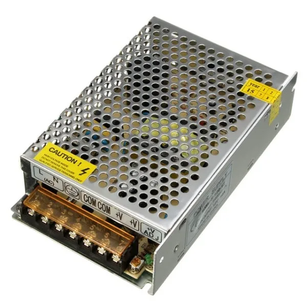
12V 10A SMPS – 120W – DC Metal Power Supply
A stable 12V regulated supply is essential for good XR2206 performance. This 120W SMPS provides clean DC with minimal ripple for accurate waveform generation.
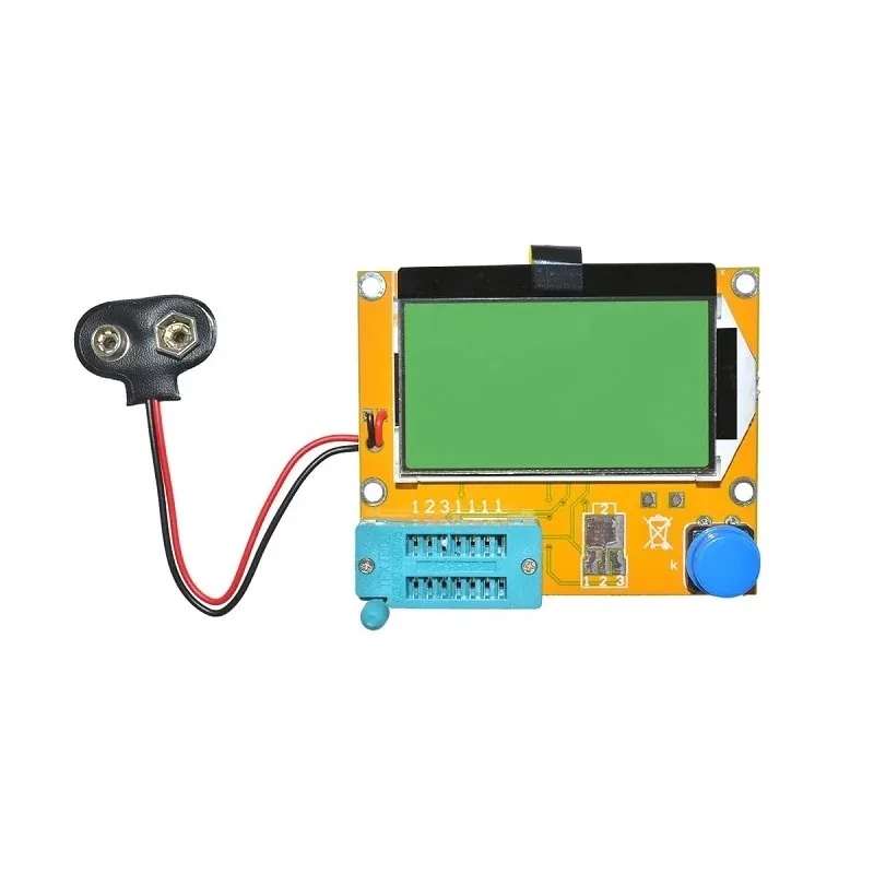
9V Battery Operated LCR-T4 12864 LCD Graphical Transistor Tester
Verify your resistors, capacitors, and transistors before building. This LCR-T4 tester identifies component values and polarity instantly — indispensable for any electronics lab.
Frequently Asked Questions
Q1: Can I run the XR2206 from a 9V battery?
The XR2206’s datasheet specifies a minimum supply voltage of 10V, so a standard 9V battery is slightly below specification. In practice, many hobbyists use a fresh 9V alkaline (which actually starts at ~9.5V) and find it works, but output amplitude will be reduced and frequency accuracy may drift as the battery discharges. For reliable lab use, stick to a regulated 12V supply.
Q2: Why is my sine wave distorted?
Sine wave distortion in the XR2206 is usually caused by the waveshaping trimmers (pins 13-14) being misadjusted, or by the timing resistor being set too low (below 1kΩ). Try increasing the timing resistor value and carefully trimming the 200Ω pot between pins 13 and 14. Also check that your decoupling capacitor is in place — a noisy supply rail will corrupt the sine output.
Q3: How do I get a triangle wave from the XR2206?
The triangle wave is an internal signal in the XR2206. To access it, connect a resistor (around 10kΩ) from the triangle output internal node — this is done by adjusting the pins 13-14 trimmer to fully one side (fully clockwise or fully counter-clockwise depending on your circuit). Some XR2206 circuit designs expose this via a specific trimmer setting. Alternatively, use a dedicated op-amp integrator to convert the square wave output into a triangle wave.
Q4: What is FSK mode and how do I use it?
FSK (Frequency Shift Keying) mode uses both timing resistor inputs (pins 7 and 8). Connect separate resistors to each pin to set two distinct frequencies. The FSK input (pin 9) selects between them with a logic-level signal. When the FSK pin is high, the frequency is set by pin 7’s resistor; when low, it uses pin 8’s resistor. This is ideal for generating RTTY (radio teletype) or simple binary FSK data modulation signals.
Q5: Can I achieve the XR2206 function with Arduino or a microcontroller?
Yes — Arduino with a dedicated DDS module (like the AD9833) can generate sine, triangle, and square waves digitally. However, the XR2206 has advantages: it needs no programming, its sine wave is analogue (lower distortion at audio frequencies), and the circuit is simpler for pure analogue applications. DDS modules are better for precise frequency control and high-frequency synthesis above 1 MHz.
Ready to Build Your XR2206 Waveform Generator?
Get all the passive components — capacitors, resistors, jumper wires, and prototype boards — at Zbotic. We ship across India with fast delivery to Mumbai, Delhi, Bangalore, Chennai, Hyderabad, and 19,000+ pin codes.


Add comment