
If you’ve ever shopped for a stepper motor, you’ve likely encountered the terms bipolar and unipolar — often without a clear explanation of what they mean. These aren’t just marketing terms; they describe fundamentally different winding configurations that affect how the motor is driven, what drivers you can use, how much torque it produces, and how complex your wiring is.
In this guide, we’ll break down the bipolar vs unipolar stepper motor debate completely — from the physics of how they work, to practical driver selection, wiring diagrams, and which type to choose for common maker projects like 3D printers, CNC machines, and robotic arms.
How Stepper Motors Work
A stepper motor is a brushless DC motor that divides a full rotation into a fixed number of equal steps. Unlike regular DC motors that spin continuously when voltage is applied, a stepper motor moves by energizing electromagnets (coils/windings) in sequence. Each energization step rotates the shaft by a precise angle — typically 1.8° per step (giving 200 steps/revolution) for most hobby and industrial steppers.
The motor’s rotor (often a permanent magnet or toothed ferromagnetic disc) is attracted to the currently energized stator pole. By switching the energized pole from coil A to coil B to coil C in sequence, the rotor “chases” the magnetic field around — producing controlled rotation.
The fundamental difference between bipolar and unipolar motors lies in how the current flows through the coils to produce this magnetic field reversal.
Unipolar Stepper Motors Explained
A unipolar stepper motor has two coil windings per phase, each with a center tap. This gives the motor either 5 wires (two phases with a shared center tap) or 6 wires (two phases with separate center taps), or even 8 wires (all taps brought out separately).
The name “unipolar” refers to the fact that current flows in only one direction through each half-winding. To reverse the magnetic field direction, you switch to the other half of the same winding (the other side of the center tap) — rather than reversing current through the full winding.
Unipolar Winding Configuration (4-phase, 5-wire example):
- Wire 1: Phase A+
- Wire 2: Center tap (common, connected to +V)
- Wire 3: Phase A–
- Wire 4: Phase B+
- Wire 5: Phase B–
How it’s driven: The center tap is connected to positive supply voltage. Each of the four outer wires is connected to a low-side switch (transistor or MOSFET) that pulls it to GND. Activating A+ energizes one half of coil A. Activating A– energizes the other half, creating a reversed magnetic field — without ever reversing current direction in any single transistor.
Key implication: At any moment, only half the winding is active. This means only half the copper is contributing to torque production.
The classic example of a unipolar stepper motor popular in Indian maker projects is the 28BYJ-48 — the blue 5V stepper motor commonly sold with the ULN2003 driver board. It has 5 wires and is a textbook unipolar motor.
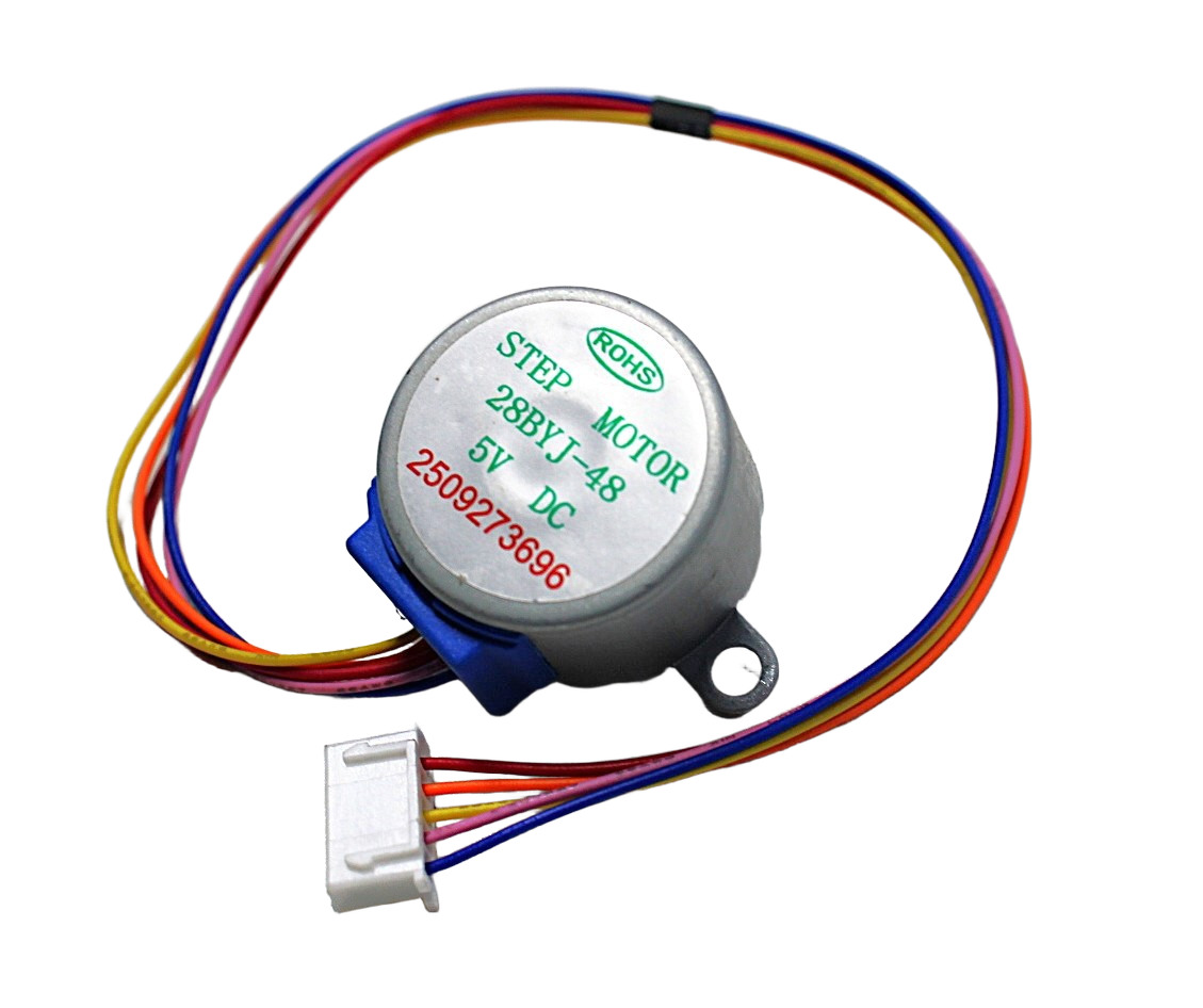
28BYJ-48 5V Stepper Motor
The quintessential beginner unipolar stepper motor. Driven via ULN2003 driver, great for learning stepper control with Arduino. Geared 1:64 reduction, 512 steps per revolution in half-step mode.
Bipolar Stepper Motors Explained
A bipolar stepper motor has one winding per phase (typically two phases = 4 wires total). There is no center tap. To reverse the magnetic field in a coil, the current direction through the entire coil must be reversed — hence “bipolar” (both polarities flow through the same wire).
Bipolar Winding Configuration (2-phase, 4-wire):
- Wire 1: Coil A+
- Wire 2: Coil A–
- Wire 3: Coil B+
- Wire 4: Coil B–
How it’s driven: A bipolar motor requires an H-bridge per coil — a circuit that can apply voltage in both directions across each winding. Dedicated stepper driver ICs like the A4988 or DRV8825 contain two H-bridges internally and handle all the direction logic. You simply provide STEP and DIR signals.
Key implication: Because the full winding is always active (not just half), the magnetic field per watt of power is stronger. Bipolar motors produce approximately 40% more torque than an equivalent unipolar motor using only the outer windings.
All modern CNC stepper motors (NEMA 17, NEMA 23, etc.) and 3D printer motors are bipolar motors with 4 wires. The NEMA 17 is the most common bipolar stepper in the maker community.

NEMA17 5.6 kg-cm Stepper Motor with Detachable Cable (D-Type Shaft)
A high-quality bipolar NEMA17 motor — the standard for 3D printers and CNC routers. 5.6 kg-cm holding torque, detachable cable for clean routing, and D-type shaft for secure pulley mounting.
Side-by-Side Comparison
| Feature | Unipolar | Bipolar |
|---|---|---|
| Number of wires | 5, 6, or 8 | 4 (always) |
| Current direction per coil | One direction (unidirectional) | Both directions (bidirectional) |
| Driver complexity | Simple (ULN2003, 4 transistors) | More complex (H-bridge, A4988) |
| Torque (same size motor) | Lower (~70% of bipolar) | Higher (~40% more) |
| Power efficiency | Lower (half winding active) | Higher (full winding active) |
| Common examples | 28BYJ-48, older printers | NEMA17, NEMA23, all modern CNC |
| Best for | Learning, light loads, low cost | CNC, 3D printing, robotics, precision |
| Popular drivers | ULN2003, L293D | A4988, DRV8825, TMC2208 |
How to Identify Your Stepper Motor Type
When you receive an unmarked stepper motor (a common situation with surplus or generic motors), here’s how to identify whether it’s unipolar or bipolar:
Step 1: Count the wires
- 4 wires: Almost certainly bipolar. Test pairs to find the two coils.
- 5 wires: Unipolar with shared center tap. One wire will read ~half resistance to all others (that’s the common).
- 6 wires: Could be unipolar (2 center taps) or a bipolar with two separate winding leads each. Test to determine.
- 8 wires: Bipolar with all leads independent — most flexible, can be wired bipolar, unipolar, or series/parallel bipolar.
Step 2: Use a multimeter (resistance test)
Set your multimeter to resistance (Ω) mode. Probe pairs of wires:
- Wires within the same coil will show resistance (typically 5–50Ω depending on motor)
- Wires from different coils will show open (infinite resistance)
- For a 5-wire unipolar: the center tap wire shows resistance to 4 other wires; each pair of outer wires shows 2× the resistance of center-to-outer
Driver Selection Guide
Drivers for Unipolar Stepper Motors
ULN2003A Driver Board: The go-to for 28BYJ-48 motors. Contains 7 Darlington transistor pairs, each capable of 500 mA. Simple 4-pin control interface. Perfect for low-torque unipolar applications.
L293D / L298N: Can drive unipolar motors (use only the 4 outer wires, ignore center taps) or be used as H-bridge for bipolar.
Drivers for Bipolar Stepper Motors

A4988 Stepper Motor Driver Controller Board (RED)
The most widely used bipolar stepper driver. Built-in microstepping (up to 1/16), current limiting via trim pot, thermal shutdown protection. The default choice for NEMA17 motors in Arduino CNC and 3D printer projects.
The A4988 is the standard for bipolar NEMA17 motors. Key features:
- Max current: 2A per coil (with heat sink)
- Microstepping: Full, Half, 1/4, 1/8, 1/16
- Motor supply voltage: 8–35V
- Logic supply: 3.3V or 5V
- Control: Just two Arduino pins (STEP and DIR)
Driver comparison for bipolar motors:
- A4988: 2A, up to 1/16 microstepping, affordable, standard choice
- DRV8825: 2.5A, up to 1/32 microstepping, higher voltage capability
- TMC2208/TMC2209: Silent stepper drivers, UART programmable, excellent for 3D printers
Torque Analysis: Which Is Stronger?
Torque in a stepper motor is proportional to the ampere-turns in the active winding — that is, current × number of wire turns. Here’s the key insight:
In a unipolar motor, at any given moment, only half the total winding turns are active (one half-winding). In a bipolar motor, the full winding is always active. Assuming the same amount of copper wire in the motor:
- Bipolar: All turns active → maximum magnetic field → maximum torque per amp
- Unipolar: Half turns active → half the magnetic field → lower torque per amp
In practice, this means a bipolar motor produces approximately 30–40% more holding torque than an equivalent unipolar motor at the same current.
However, unipolar motors can partly compensate by running both half-windings simultaneously (“full coil” mode). But this requires care to avoid overheating, since the center tap arrangement means more dissipation.
6-Wire Motors: The Hybrid Option
6-wire stepper motors bring out both the full coil leads AND the center taps. This makes them extremely flexible:
- Used as unipolar: Connect center taps to +V, use 4 outer wires with ULN2003 or similar. Simple driver, less torque.
- Used as bipolar (center taps ignored): Leave center taps unconnected, treat as a 4-wire bipolar motor. More torque, needs H-bridge driver.
- Used as bipolar series: Connect A–center to B–center (or use series configuration). Higher inductance, higher torque at low speeds, needs higher voltage.
6-wire motors give you the best of both worlds during development — you can prototype with a simpler unipolar driver and then switch to bipolar later for better performance without changing the motor.
Which Should You Choose?
Choose Unipolar (28BYJ-48 style) if:
- You’re a beginner learning stepper motor control
- Your load is light (small mechanisms, clock hands, light positioning)
- You want the simplest possible driver circuit (ULN2003)
- Budget is the primary constraint
- Speed is not critical (28BYJ-48 is slow due to its high gear reduction)
Choose Bipolar (NEMA17/NEMA23 style) if:
- You’re building a 3D printer, CNC router, laser cutter, or similar machine
- You need significant torque (1 kg-cm and above)
- You need microstepping for smooth motion
- You need higher speeds
- You’re using an Arduino CNC shield or RAMPS board (all designed for A4988/DRV8825)
Frequently Asked Questions
Can I use an A4988 to drive a unipolar stepper motor?
Yes — if your unipolar motor is a 6-wire or 8-wire type, simply leave the center tap wires disconnected and use the 4 outer wires as a bipolar motor. The A4988 will drive it correctly. Do not connect center taps to the A4988’s motor terminals.
Why do 3D printers all use bipolar stepper motors?
3D printers need precise, high-torque movement over long duty cycles. Bipolar motors offer more torque per unit of motor size, work efficiently with the microstepping drivers (A4988, DRV8825, TMC2208) used on RAMPS and similar boards, and NEMA17 is an industry-standard form factor that fits standard motor mounts and pulleys.
Is NEMA17 always bipolar?
NEMA17 refers only to the mechanical faceplate size (42 × 42 mm), not the winding type. However, virtually all NEMA17 motors sold today are bipolar (4-wire). Unipolar NEMA17 motors exist (6 or 8 wires) but are uncommon in hobby/maker supply.
What is microstepping and which motor type supports it?
Microstepping divides each full step into smaller sub-steps by applying partially overlapping current to both coils simultaneously. This produces smoother motion and reduces vibration. Microstepping is primarily associated with bipolar motors and dedicated drivers (A4988, DRV8825). Unipolar motors can also be microstepped but this is less common in practice because the required drivers are more complex.
Can a unipolar motor be converted to bipolar?
Yes, for 5-wire unipolar motors with a shared center tap: you cannot easily convert them (the center tap wire cannot be removed). For 6-wire motors: simply disconnect the center tap wires and use the 4 outer wires as a bipolar motor with an A4988. For 8-wire motors: you have maximum flexibility to wire as bipolar series, parallel, or unipolar.
Which stepper motor is better for a robotic arm?
For robotic arms, bipolar NEMA17 motors with A4988 or DRV8825 drivers are the standard choice. They offer the torque density needed to move arm segments, support microstepping for smooth motion, and integrate easily with Arduino + CNC shield setups. The NEMA17 5.6 kg-cm is a good starting point for smaller arms.
Conclusion
The bipolar vs unipolar debate comes down to a simple trade-off: unipolar motors are simpler to drive but produce less torque; bipolar motors need H-bridge drivers but are significantly more powerful and efficient.
For 95% of modern maker projects — especially anything involving CNC, 3D printing, or robotics — bipolar NEMA17 motors with an A4988 driver are the right choice. For learning, experimenting with small mechanisms, or ultra-low-budget builds, the 28BYJ-48 unipolar motor with its ULN2003 board remains an excellent starting point.
Explore Zbotic’s full range of stepper motors and drivers to find the perfect match for your next precision motion project!


Add comment