
Voltage Regulator 7805 vs LM317: Linear Regulator Guide
Every electronics project needs a stable power supply, and two of the most widely used components for the job are the 7805 and LM317 voltage regulators. If you are building a power supply for an Arduino, charging circuit, or any regulated DC project, this complete voltage regulator 7805 vs LM317 linear regulator guide will help you make the right choice. Both are linear regulators — meaning they dissipate the excess voltage as heat — but they serve different purposes and excel in different applications. From college labs in Jaipur to professional workshops in Hyderabad, these two ICs are the backbone of countless Indian electronics projects. Let us explore them in detail.
How Linear Voltage Regulators Work
A linear voltage regulator acts as a variable resistance in series between the input voltage and the output. It continuously adjusts its internal resistance to maintain a constant output voltage regardless of input voltage variations or load current changes. The excess voltage (VIN − VOUT) drops across the regulator’s internal pass transistor, and the power dissipated is:
Pdissipated = (VIN − VOUT) × ILOAD
This is the fundamental limitation of linear regulators: they waste energy as heat. A circuit regulating 12V input down to 5V while supplying 500 mA dissipates (12−5) × 0.5 = 3.5 W — requiring a heatsink. The efficiency is only VOUT/VIN × 100% = 42% in this case. Compare this to a switching regulator at 85–95% efficiency.
Despite low efficiency, linear regulators are preferred for:
- Very low noise applications (audio, precision sensing, RF)
- Simple circuits with few components
- Low voltage drop applications (small VIN − VOUT)
- Applications where EMI from switching regulators is unacceptable
The 7805: Fixed 5V Regulator Deep Dive
The 7805 belongs to the 78xx series of fixed positive voltage regulators (7812 = 12V, 7809 = 9V, 7815 = 15V, etc.). The output voltage is factory-set and requires no external components to set — just input, output, and ground connections with small filter capacitors.
7805 Pinout (TO-220 package)
- Pin 1 (left): INPUT (VIN) — connect to unregulated DC supply
- Pin 2 (middle): GROUND — connect to circuit ground
- Pin 3 (right): OUTPUT (VOUT) — regulated 5V output
Memory trick: facing the flat face with the tab at the top, pins are Input–Ground–Output from left to right.
7805 Key Specifications
| Parameter | Value |
|---|---|
| Output voltage | 5.0 V ± 2–4% |
| Input voltage range | 7 V minimum to 35 V maximum |
| Maximum output current | 1.5 A (with heatsink) |
| Dropout voltage | ~2 V (VIN must be ≥ 7 V) |
| Quiescent current | ~5 mA |
| Line regulation | ~4 mV typical |
| Load regulation | ~10 mV typical |
| Output noise | ~40 µVRMS (10 Hz – 100 kHz) |
| Protection | Thermal shutdown, current limiting, SOA protection |
Standard 7805 Circuit
The simplest functional circuit needs just two capacitors:
- 0.33 µF (or larger) ceramic/film capacitor from INPUT to GND (stabilises input, especially if far from main filter cap)
- 0.1 µF ceramic capacitor from OUTPUT to GND (improves transient response)
For better filtering, add a 10 µF electrolytic on the output in parallel with the 0.1 µF ceramic.

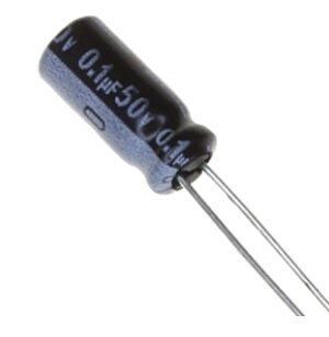
0.1µF Ceramic Capacitor – Pack of 50
The essential 100 nF bypass capacitor for 7805 and LM317 regulator circuits. Place one on the output pin of any voltage regulator to improve transient response.
The LM317: Adjustable Regulator Deep Dive
The LM317 is an adjustable positive voltage regulator. Its output voltage is set by an external resistor divider, making it versatile for applications requiring voltages other than 5V — or applications where the output voltage must be tunable with a potentiometer.
LM317 Pinout (TO-220 package)
- Pin 1 (left): ADJUST — connects to the resistor divider feedback network
- Pin 2 (middle): OUTPUT (VOUT) — regulated adjustable output
- Pin 3 (right): INPUT (VIN) — connect to unregulated DC supply
Note: The LM317 pinout is NOT the same as the 7805! The middle pin is OUTPUT on the LM317 but GROUND on the 7805. Swapping these is a common and damaging mistake.
LM317 Output Voltage Formula
VOUT = 1.25 × (1 + R2/R1)
Where R1 and R2 are the resistors in the voltage-setting divider connected from OUTPUT to ADJUST (R1) and from ADJUST to GND (R2). The reference voltage between OUTPUT and ADJUST is always 1.25 V (VREF).
Standard design procedure: Fix R1 = 240 Ω (or 220 Ω), then calculate R2 for the desired output:
R2 = R1 × (VOUT/1.25 − 1)
Examples:
- 3.3 V: R1 = 240 Ω, R2 = 240 × (3.3/1.25 − 1) = 240 × 1.64 = 394 Ω → use 390 Ω
- 9 V: R1 = 240 Ω, R2 = 240 × (9/1.25 − 1) = 240 × 6.2 = 1488 Ω → use 1.5 kΩ
- 12 V: R1 = 240 Ω, R2 = 240 × (12/1.25 − 1) = 240 × 8.6 = 2064 Ω → use 2.2 kΩ
LM317 Key Specifications
| Parameter | Value |
|---|---|
| Output voltage range | 1.25 V to 37 V (adjustable) |
| Input voltage range | VOUT + 3 V minimum to 40 V maximum |
| Maximum output current | 1.5 A (with heatsink) |
| Dropout voltage | ~3 V typical |
| Adjust pin current | ~50–100 µA (affects output accuracy) |
| Line regulation | ~0.01%/V typical |
| Protection | Thermal shutdown, current limiting, SOA protection |
For a variable bench power supply, replace R2 with a 10 kΩ potentiometer in series with a 240 Ω resistor (to set minimum output to 1.25 V). This gives you a continuously adjustable 1.25–37 V supply.
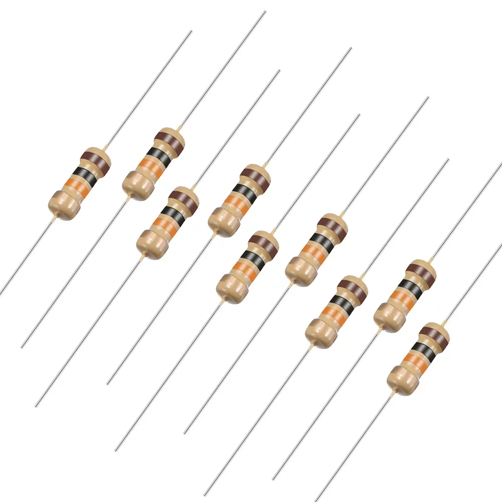
10 Ohm 0.25W Carbon Film Resistor – Pack of 50
Precision resistors for LM317 voltage-setting dividers. Use the appropriate resistance values to dial in your exact output voltage as per the formula above.
7805 vs LM317: Head-to-Head Comparison
| Feature | 7805 | LM317 |
|---|---|---|
| Output voltage | Fixed 5 V (78xx = fixed family) | Adjustable 1.25–37 V |
| External components needed | 2 capacitors only | 2 resistors + 2–3 capacitors |
| Minimum input voltage | 7 V | VOUT + 3 V |
| Circuit simplicity | Very simple (3-pin, no math) | Slightly more complex |
| Flexibility | Limited (fixed family only) | Very flexible |
| Cost | Very cheap (₹5–10) | Slightly higher (₹10–20) |
| Best for | Arduino 5V, MCU supplies, logic ICs | Variable bench supply, battery charger, custom voltages |
| Negative version | 79xx series (7905, 7912, etc.) | LM337 (negative adjustable) |
Practical Circuit Designs
Classic 5V Arduino Power Supply (7805)
Transform a 9V wall adapter or 12V SMPS into a regulated 5V supply for Arduino Uno:
- Input: 9–12V DC from power supply
- 1000 µF electrolytic cap from input to GND (main filter)
- 0.33 µF ceramic cap from input to GND (close to 7805)
- 7805 regulator
- 0.1 µF ceramic cap from output to GND
- 470 µF electrolytic from output to GND (improved transient response)
- LED + 470 Ω resistor from output to GND as power indicator
Adjustable 1.25–15V Lab Supply (LM317)
- Input: 18V DC from transformer + bridge rectifier
- 2200 µF/25V electrolytic cap on input
- LM317 regulator
- R1 = 240 Ω from OUTPUT to ADJUST
- 10 kΩ potentiometer + 100 Ω in series from ADJUST to GND (100 Ω ensures minimum output is 1.25 V)
- 10 µF electrolytic from ADJUST to GND (improves ripple rejection by ~15 dB)
- 0.1 µF from OUTPUT to GND
- 1N4007 diode from OUTPUT to INPUT (protects against output capacitor discharge)
- 1N4007 diode from OUTPUT to ADJUST (protects against adjust cap discharge)
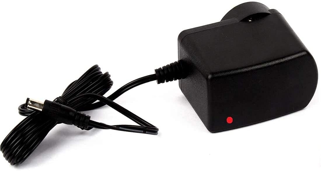
12V 2A Power Supply with 5.5mm DC Plug
A ready-made 12V 2A wall adapter — the ideal input source for a 7805 or LM317 circuit. The 12V input gives enough headroom above the regulator dropout voltage.
Thermal Management and Heatsinking
The most important practical consideration for both regulators is heat. The thermal resistance of a bare TO-220 package (junction to ambient) is approximately 50°C/W. At 3.5 W dissipation, the junction temperature rises by 175°C above ambient — far exceeding the 125°C maximum junction temperature. A heatsink is mandatory for any sustained load above a few hundred milliamperes.
Estimating heatsink requirements:
- Calculate power dissipation: P = (VIN − VOUT) × ILOAD
- Determine allowable temperature rise: TJ(max) − Tambient = 125 − 50 = 75°C
- Total thermal resistance needed: Rθ = ΔT / P = 75 / 3.5 ≈ 21°C/W
- Subtract junction-to-case (≈3°C/W) and case-to-heatsink with thermal paste (≈1°C/W)
- Heatsink required: ≤ 17°C/W — a medium-sized aluminium clip-on heatsink
Practical tips:
- Always use thermal paste between the regulator body and heatsink
- Ensure the heatsink metal tab is insulated from circuit board ground if the tab is electrically connected to a voltage other than GND (the 7805 tab = GND; the LM317 tab = OUTPUT)
- Improve efficiency by minimising VIN − VOUT. For a 5V output, use a 7–8V input rather than 12V to halve the power dissipation
When to Use a Switching Regulator Instead
Linear regulators like the 7805 and LM317 are not always the right choice. Consider a switching (buck/boost/SMPS) regulator when:
- Efficiency matters: Battery-powered projects where battery life is important. A 5V regulator on a 12V battery with 500 mA load: linear = 42% efficient (3.5 W heat), buck converter = 90% efficient (0.33 W heat)
- High power: Above 1.5 A, the LM317/7805 are at their limit. Buck modules (LM2596, XL4016, MP1584) handle 3–8 A easily
- Input/output voltage difference is large: Dropping 24V to 5V through a 7805 at 1 A dissipates 19 W — requiring a massive heatsink
- Buck-boost needed: When the output voltage must be higher or lower than input depending on conditions (e.g., Li-ion battery discharging from 4.2 V to 3 V while powering a 3.3 V circuit)
The best approach for Indian makers on a budget: use a cheap DC-DC buck converter module (₹50–150 each) for efficient high-current applications, and reserve linear regulators (7805/LM317) for low-current, low-noise, and simple circuits.
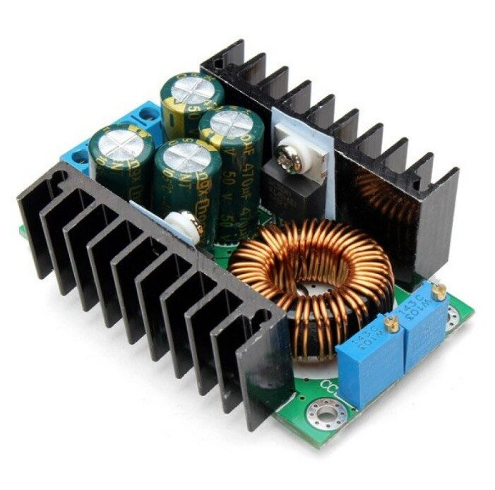
300W 10A DC-DC Step-down Buck Converter – Adjustable
When a 7805 or LM317 is not enough, step up to this efficient buck converter. Handles up to 10 A with adjustable output — perfect for high-power projects and lab benches.
0.1µF 50V Capacitor – Pack of 50
Essential output decoupling capacitors for 7805 and LM317 regulators. 50V rating gives ample safety margin for use on the input side as well.
Frequently Asked Questions
Can I use a 7805 to power an ESP32 or Raspberry Pi?
The ESP32 can draw 250–500 mA during Wi-Fi transmissions. A 7805 can handle this, but check that your input supply can provide sufficient current. A Raspberry Pi 4 draws up to 3 A — far beyond the 7805’s 1.5 A limit. Also note: Raspberry Pi requires a very stable 5.1 V, and the 7805’s ±4% tolerance (4.8–5.2 V) is marginal. A dedicated 5V switching adapter is better for Raspberry Pi.
Why does my 7805 get so hot even with a small load?
Even a small load can cause significant heating if VIN is much higher than VOUT. At 100 mA load with 12V input: P = (12−5) × 0.1 = 0.7 W. The 7805 junction temperature rises by 0.7 W × 50°C/W = 35°C above ambient — hot to touch but within safe limits. Reduce input voltage to the minimum needed (7–8V for 5V output) to minimise heat. Always add a heatsink if the body feels uncomfortably hot.
Is LM317 better than 7805?
Neither is universally better. The 7805 is simpler and cheaper for fixed 5V applications. The LM317 is more flexible (any voltage from 1.25–37 V) and has slightly better regulation specifications. Choose the 7805 when you need exactly 5V with minimal complexity. Choose the LM317 when you need a different or adjustable voltage, or when you want slightly better performance.
Can I connect two 7805 regulators in parallel to get 3A?
Not directly. Linear regulators do not share current well in parallel due to tolerance differences — one regulator will carry more load than the other. To increase current capacity, use a single 7805 with an external pass transistor (such as a 2N3055 or TIP3055), which allows the 7805 to control a high-current NPN while the transistor handles the load current. Alternatively, use a higher-rated regulator like the LM338 (5 A) or a switching regulator module.
What is the difference between LM317 and LM7805 in terms of noise?
Both have similar noise characteristics for general electronics use (~40–100 µVRMS output noise). For audio or precision measurement applications, a dedicated low-noise LDO (Low Dropout) regulator like the LT1962, LP5907, or ADP7142 is a better choice. These can achieve noise levels below 10 µVRMS — 10× quieter than standard linear regulators.
Power Up Your Next Project
Whether you need a rock-solid 5V supply for your Arduino or a versatile adjustable bench supply, the 7805 and LM317 are trustworthy workhorses that have powered generations of electronics projects. Get your regulators, capacitors, resistors, and power supplies from Zbotic — India’s go-to store for electronics components, delivered fast to your doorstep.


Add comment