
When building a small autonomous robot, wheeled platform, or any battery-powered motor project with an ESP32, the choice of motor driver matters enormously. The DRV8833 motor driver from Texas Instruments has become a favourite for ESP32-based projects because it packs two H-bridges into a tiny footprint, operates down to 2.7V (compatible with 3.3V ESP32 logic directly), draws almost zero quiescent current in sleep mode, and includes built-in current limiting and thermal protection.
This tutorial covers everything you need to know to use the DRV8833 for dual DC motor control with an ESP32 — from hardware wiring to smooth PWM speed control code with acceleration profiles.
DRV8833 Overview & Key Specs
The DRV8833 is a dual H-bridge motor driver IC from Texas Instruments designed specifically for the requirements of battery-powered portable applications. Here are its key specifications:
| Parameter | Value |
|---|---|
| Operating voltage (VM) | 2.7V to 10.8V |
| Logic supply (VCC) | 1.8V to 7V |
| Output current (per channel, continuous) | 1.5A RMS |
| Output current (peak, per channel) | 2A |
| Number of H-bridge channels | 2 (can parallel for one motor at 3A) |
| Current limiting (ITRIP) | Via external sense resistor |
| Sleep mode current | <1 µA |
| Thermal shutdown | Yes (TSD at ~150°C) |
| Undervoltage lockout | Yes |
| Package | WQFN-16 (IC) or breakout module |
DRV8833 vs L298N vs TB6612FNG
Choosing a motor driver for an ESP32 project is not just about current rating. Here is how the DRV8833 compares to other popular options:
| Feature | DRV8833 | L298N | TB6612FNG |
|---|---|---|---|
| Max voltage | 10.8V | 46V | 15V |
| Max current/channel | 1.5A (2A peak) | 2A (4A peak) | 1.2A (3.2A peak) |
| 3.3V ESP32 compatible | Yes (native) | Needs 5V logic | Yes |
| Sleep current | <1 µA | ~36 mA | ~1 µA |
| Efficiency | High (MOSFET) | Low (bipolar, 2V drop) | High (MOSFET) |
| Built-in current limit | Yes | No | No |
| Best for | Battery robots, small motors | High voltage motors, bench power | Balance of features |
The L298N’s 2V voltage drop (caused by its bipolar transistors) becomes significant for 3.3V or 5V motors — you lose 40–60% of available voltage. The DRV8833’s MOSFET design has a much lower drop (~0.3V), making it far more efficient for small robot applications.
Pin Description & Module Layout
The DRV8833 breakout module (available from Pololu, Adafruit, and similar suppliers) typically exposes these pins:
| Pin | Direction | Description |
|---|---|---|
| VCC (VM) | Power in | Motor supply voltage 2.7–10.8V |
| GND | Power in | Ground — common with ESP32 GND |
| AIN1 | Input | Channel A input 1 (PWM or logic) |
| AIN2 | Input | Channel A input 2 (PWM or logic) |
| BIN1 | Input | Channel B input 1 (PWM or logic) |
| BIN2 | Input | Channel B input 2 (PWM or logic) |
| AOUT1, AOUT2 | Output | Channel A motor terminals |
| BOUT1, BOUT2 | Output | Channel B motor terminals |
| SLP (nSLEEP) | Input | Sleep pin — LOW = sleep, HIGH = active (often pulled HIGH on module) |
| FLT (nFAULT) | Output | Fault indicator — LOW = fault condition (OC or thermal) |
Wiring DRV8833 to ESP32
The DRV8833’s 1.8–7V logic supply means ESP32’s 3.3V GPIO pins connect directly — no level shifter required. This is a major advantage over the L298N which needs 5V logic.
| DRV8833 Module Pin | ESP32 Connection |
|---|---|
| VM (motor power) | Battery + / 5V supply |
| GND | ESP32 GND + Battery − |
| AIN1 | GPIO 27 |
| AIN2 | GPIO 26 |
| BIN1 | GPIO 25 |
| BIN2 | GPIO 33 |
| SLP | GPIO 32 (or tie to 3.3V if sleep not needed) |
| FLT | GPIO 34 (input only pin, with pull-up) |
Important ESP32 note: Avoid GPIO pins 6–11 (connected to flash memory), GPIO 34–39 (input only), and check your specific board’s pin map. The GPIOs listed above work on most ESP32 DevKit boards.
Control Modes: IN/IN vs PH/EN
The DRV8833 supports two control input modes depending on how you apply the signals:
IN/IN mode (default on most modules)
Both input pins are driven independently. The truth table is:
| xIN1 | xIN2 | Motor State |
|---|---|---|
| 0 | 0 | Coast (both outputs high-Z) |
| 0 | 1 | Reverse |
| 1 | 0 | Forward |
| 1 | 1 | Brake (both outputs LOW) |
For speed control in IN/IN mode: apply PWM to one pin while the other is HIGH or LOW for direction. Apply PWM to AIN1 with AIN2 = LOW for forward speed control.
ESP32 LEDC PWM Configuration
The ESP32 does not use Arduino’s analogWrite(). Instead, it has a dedicated LEDC (LED Controller) peripheral that generates high-resolution PWM on any GPIO pin. Here is how to configure it:
// ESP32 LEDC PWM setup
// Channel 0-15 available; channels 0-7 = high speed, 8-15 = low speed

const int FREQ = 20000;    // 20kHz — above audible range
const int RESOLUTION = 8;  // 8-bit = 0–255 range

// Motor A
const int AIN1 = 27, AIN2 = 26;
const int CH_A1 = 0, CH_A2 = 1;

// Motor B
const int BIN1 = 25, BIN2 = 33;
const int CH_B1 = 2, CH_B2 = 3;

void setup() {
  // Configure LEDC channels
  ledcSetup(CH_A1, FREQ, RESOLUTION);
  ledcSetup(CH_A2, FREQ, RESOLUTION);
  ledcSetup(CH_B1, FREQ, RESOLUTION);
  ledcSetup(CH_B2, FREQ, RESOLUTION);

  // Attach channels to GPIO pins
  ledcAttachPin(AIN1, CH_A1);
  ledcAttachPin(AIN2, CH_A2);
  ledcAttachPin(BIN1, CH_B1);
  ledcAttachPin(BIN2, CH_B2);
}

// speed: -255 to +255
void motorA(int speed) {
  if(speed > 0) {
    ledcWrite(CH_A1, speed);
    ledcWrite(CH_A2, 0);
  } else if(speed < 0) {
    ledcWrite(CH_A1, 0);
    ledcWrite(CH_A2, -speed);
  } else {
    ledcWrite(CH_A1, 0);
    ledcWrite(CH_A2, 0);   // Coast
  }
}

void motorB(int speed) {
  if(speed > 0) {
    ledcWrite(CH_B1, speed);
    ledcWrite(CH_B2, 0);
  } else if(speed < 0) {
    ledcWrite(CH_B1, 0);
    ledcWrite(CH_B2, -speed);
  } else {
    ledcWrite(CH_B1, 0);
    ledcWrite(CH_B2, 0);   // Coast
  }
}
Complete Arduino IDE Code for ESP32
// DRV8833 + ESP32 complete robot base control
// Tested with ESP32 DevKit v1, Arduino IDE 2.x with ESP32 board package

#include <Arduino.h>

// Pin definitions
#define AIN1  27
#define AIN2  26
#define BIN1  25
#define BIN2  33
#define SLP   32
#define FLT   34

// LEDC channels
#define CH_AIN1 0
#define CH_AIN2 1
#define CH_BIN1 2
#define CH_BIN2 3

#define PWM_FREQ 20000
#define PWM_RES  8

void drv_init() {
  ledcSetup(CH_AIN1, PWM_FREQ, PWM_RES);
  ledcSetup(CH_AIN2, PWM_FREQ, PWM_RES);
  ledcSetup(CH_BIN1, PWM_FREQ, PWM_RES);
  ledcSetup(CH_BIN2, PWM_FREQ, PWM_RES);
  ledcAttachPin(AIN1, CH_AIN1);
  ledcAttachPin(AIN2, CH_AIN2);
  ledcAttachPin(BIN1, CH_BIN1);
  ledcAttachPin(BIN2, CH_BIN2);
  pinMode(SLP, OUTPUT);
  pinMode(FLT, INPUT_PULLUP);
  digitalWrite(SLP, HIGH);  // Wake up driver
}

void motorA(int spd) {
  spd = constrain(spd, -255, 255);
  if(spd >= 0) { ledcWrite(CH_AIN1, spd); ledcWrite(CH_AIN2, 0); }
  else          { ledcWrite(CH_AIN1, 0); ledcWrite(CH_AIN2, -spd); }
}

void motorB(int spd) {
  spd = constrain(spd, -255, 255);
  if(spd >= 0) { ledcWrite(CH_BIN1, spd); ledcWrite(CH_BIN2, 0); }
  else          { ledcWrite(CH_BIN1, 0); ledcWrite(CH_BIN2, -spd); }
}

void brakeAll() {
  ledcWrite(CH_AIN1, 255); ledcWrite(CH_AIN2, 255);
  ledcWrite(CH_BIN1, 255); ledcWrite(CH_BIN2, 255);
}

bool checkFault() {
  return (digitalRead(FLT) == LOW); // Active low fault
}

void accelerate(int targetA, int targetB, int stepDelay) {
  int curA = 0, curB = 0;
  while(curA != targetA || curB != targetB) {
    if(curA < targetA) curA = min(curA + 5, targetA);
    if(curA > targetA) curA = max(curA - 5, targetA);
    if(curB < targetB) curB = min(curB + 5, targetB);
    if(curB > targetB) curB = max(curB - 5, targetB);
    motorA(curA);
    motorB(curB);
    delay(stepDelay);
  }
}

void setup() {
  Serial.begin(115200);
  drv_init();
  Serial.println("DRV8833 initialised");
}

void loop() {
  if(checkFault()) {
    Serial.println("FAULT detected — stopping motors");
    brakeAll();
    delay(2000);
    return;
  }

  // Forward with ramp up
  Serial.println("Forward");
  accelerate(200, 200, 20);
  delay(2000);

  // Brake
  brakeAll();
  delay(500);

  // Reverse with ramp
  Serial.println("Reverse");
  accelerate(-200, -200, 20);
  delay(2000);

  // Coast stop
  motorA(0); motorB(0);
  delay(1000);

  // Turn: left motor reverse, right motor forward
  Serial.println("Spin");
  motorA(-200); motorB(200);
  delay(600);

  motorA(0); motorB(0);
  delay(1000);
}
Sleep Mode & Power Savings
The DRV8833’s sleep mode is one of its most valuable features for battery-powered projects. When the SLP pin is pulled LOW, the driver enters a low-power state consuming less than 1µA. This is critical for robots that spend significant time stationary.
// Sleep management
void driverSleep() {
  motorA(0); motorB(0);     // Stop motors first
  delay(50);                // Wait for motor to stop
  digitalWrite(SLP, LOW);   // Enter sleep
}

void driverWake() {
  digitalWrite(SLP, HIGH);  // Wake up
  delay(1);                 // 1ms wake-up time required
}

// In main loop:
// driverSleep() before ESP32 light sleep
// driverWake() after ESP32 wakes from sleep
Combined with ESP32’s own light sleep or deep sleep modes, this allows a robot to run for days on a single LiPo charge when most of the time is spent waiting for sensor triggers rather than driving motors.
Current Limiting & Fault Handling
The DRV8833 has a built-in current limiting feature using an external current sense resistor (typically 0.2Ω on most modules). When motor current exceeds the trip point, the output is PWM-regulated to limit current instead of shutting down completely. This prevents stall conditions from destroying the motor or driver.
The nFAULT pin (active LOW) goes low when:
- Over-current protection (OCP): Triggered when current exceeds the sense resistor limit for more than ~3µs
- Thermal shutdown (TSD): Junction temperature exceeds ~150°C
- Under-voltage lockout (UVLO): VM drops below ~2.4V
In the code example above, the checkFault() function monitors nFAULT and stops the robot if a fault occurs. A robust implementation would also log the fault, attempt recovery after a cooldown period, and alert the user via Serial or an LED indicator.
Using DRV8833 with Stepper Motors
The DRV8833 can drive a single bipolar stepper motor using both H-bridge channels as coil A and coil B. This makes it useful for lightweight stepper applications without needing a dedicated stepper driver.
// DRV8833 driving a small bipolar stepper motor
// Channel A = Coil A (AIN1/AIN2 → AOUT1/AOUT2)
// Channel B = Coil B (BIN1/BIN2 → BOUT1/BOUT2)

// Full step sequence (4 steps)
const int stepSeq[4][4] = {
  {255, 0, 255, 0},   // A+, B+
  {0, 255, 255, 0},   // A-, B+
  {0, 255, 0, 255},   // A-, B-
  {255, 0, 0, 255}    // A+, B-
};

void stepMotor(int step) {
  ledcWrite(CH_AIN1, stepSeq[step][0]);
  ledcWrite(CH_AIN2, stepSeq[step][1]);
  ledcWrite(CH_BIN1, stepSeq[step][2]);
  ledcWrite(CH_BIN2, stepSeq[step][3]);
}

void runStepper(int steps, int delayMs) {
  for(int i = 0; i < steps; i++) {
    stepMotor(i % 4);
    delay(delayMs);
  }
}
This works well with small stepper motors drawing under 1.5A per coil. For larger steppers like NEMA17, use a dedicated driver like the A4988 or DRV8825.
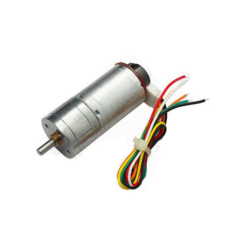
25GA-370 12V DC Gear Motor with Encoder
Pair this encoder gear motor with DRV8833 for closed-loop PID speed control on your ESP32 robot — the encoder provides feedback for precise RPM tracking.
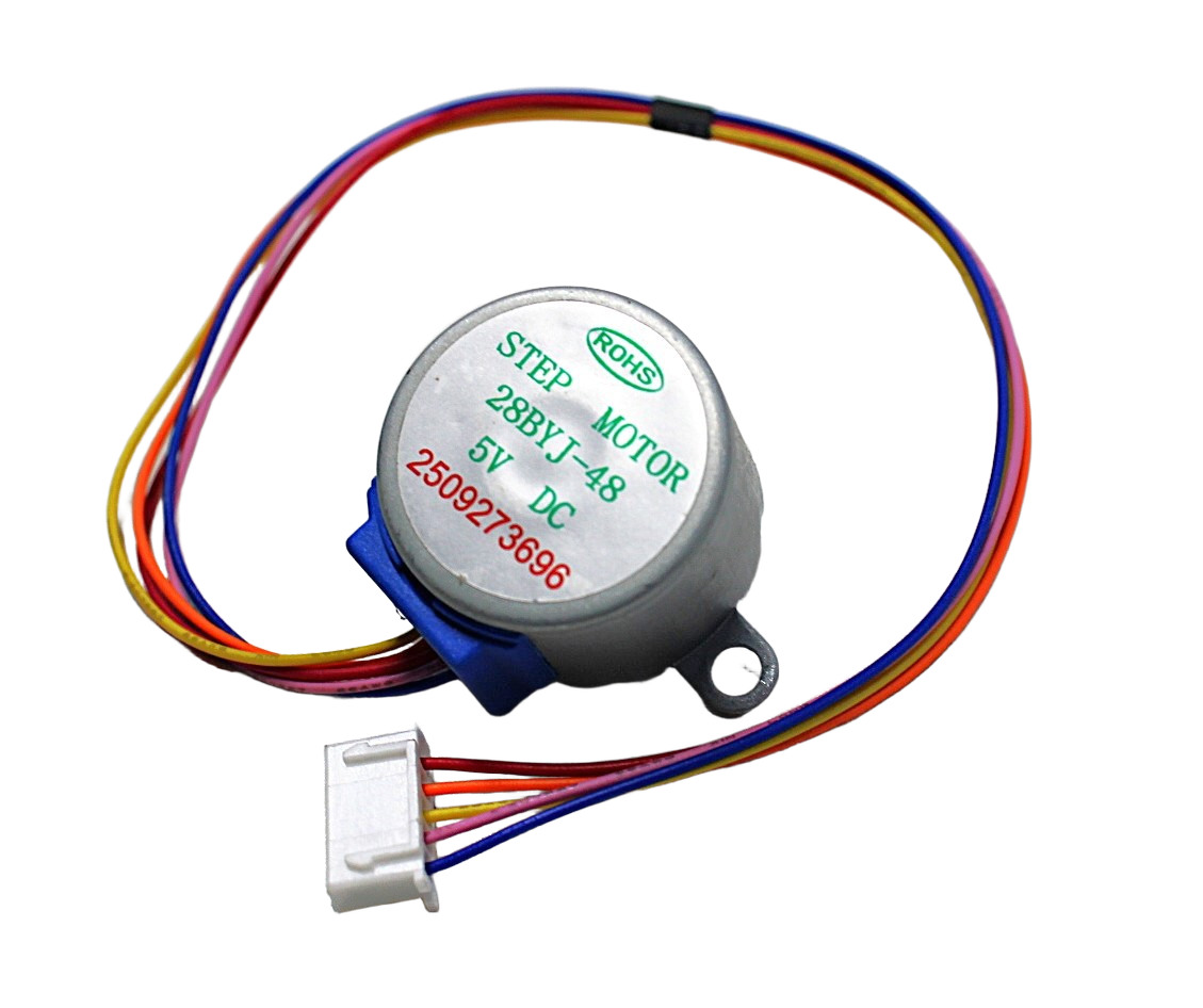
28BYJ-48 5V Stepper Motor
A low-current stepper motor compatible with DRV8833 H-bridge drive mode — great for testing stepper control concepts on your ESP32 without a dedicated stepper driver.
Recommended Products
Build your DRV8833-based robot with motors and accessories from Zbotic — fast delivery across India, with the widest range of maker components.
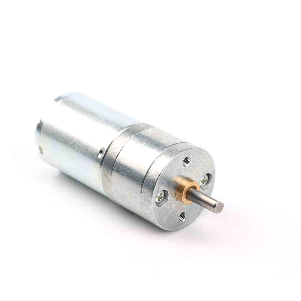
25GA-370 12V DC Reducer Gear Motor
A compact, reliable 12V gear motor — easy to drive with DRV8833 for two-wheel robot platforms, conveyor projects, and automated mechanisms.
Frequently Asked Questions
Can I use the DRV8833 with an Arduino Uno (5V logic)?
Yes. The DRV8833 logic supply accepts up to 7V, so 5V Arduino logic works perfectly. You can even power the control logic from Arduino’s 5V pin (draws minimal current) while the motor VM pin is connected to a higher voltage battery supply.
Can DRV8833 drive a single motor at higher current by paralleling both channels?
Yes. Connect AOUT1 and BOUT1 together as one motor terminal, AOUT2 and BOUT2 as the other. Drive AIN1/BIN1 with the same signal and AIN2/BIN2 with the same signal. This gives up to 3A continuous current for a single motor. Ensure the PCB traces can handle the current.
Why does my DRV8833 get hot?
The DRV8833 can handle 1.5A continuously per channel, but at those currents the IC generates significant heat. Ensure adequate airflow, stay below 80% of the rated current for reliable long-term operation, and check that your motor is not stalling frequently. If the chip is too hot to touch comfortably, reduce current or add a small heatsink pad.
What is the difference between coast and brake in DRV8833?
In coast mode (xIN1=0, xIN2=0), both output transistors are off and the motor coasts freely — it takes time to spin down due to its own inertia and friction. In brake mode (xIN1=1, xIN2=1), both low-side transistors are on, shorting the motor terminals together. The motor’s back-EMF is dissipated through this short, causing rapid deceleration. Use brake for precise stop positioning.
How do I set up DRV8833 with ESP32 using the Arduino IDE?
Install the ESP32 board package in Arduino IDE (via File → Preferences → Additional board URLs, add Espressif’s URL). Select your ESP32 board, then use ledcSetup(), ledcAttachPin(), and ledcWrite() for PWM — not analogWrite(). The complete code example in this article is tested and ready to copy-paste.
Does the DRV8833 work with 3.7V LiPo batteries?
Yes, the DRV8833 operates from 2.7V to 10.8V on the motor supply. A single 3.7V LiPo (nominal) or 4.2V (fully charged) is well within the operating range. This makes the DRV8833 ideal for compact LiPo-powered robots without any additional voltage regulation for the motor supply.
Find DC gear motors, stepper motors, and all the components you need for your next motor control project at Zbotic. Shop Motors & Actuators at Zbotic


Add comment