
If you have ever built an Arduino project only to find that your sensor is reading 3°C higher than actual temperature, or your soil moisture sensor thinks dry soil is wet — you already know the frustration of uncalibrated sensors. Sensor calibration is the single most important step between a prototype that “kind of works” and a system that can be trusted.
This comprehensive guide covers everything from the theory behind calibration to practical, step-by-step procedures for the most common sensors used in Arduino and ESP32 projects. Whether you are a student, a hobbyist, or building a professional IoT device, these techniques will save you hours of debugging and give you readings you can actually rely on.
1. Why Sensor Calibration Matters
Every sensor comes out of the factory with some degree of error. The datasheet typically specifies this as an accuracy figure — for example, the DHT11 claims ±2°C accuracy. But this is a worst-case specification. Individual units may deviate more or less, and real-world conditions (supply voltage variation, PCB layout, ageing) add further error on top.
For a room thermometer that tells you it is 27°C when it is actually 25°C, this may be acceptable. But consider these scenarios where it is not:
- A greenhouse controller that triggers irrigation 2°C too early, wasting water.
- A battery monitoring system where a 5% current reading error means you never catch an overcharge condition.
- A smart agriculture project where uncalibrated soil moisture triggers pumps unnecessarily, waterlogging crops.
Calibration maps your sensor’s raw output to a known, accurate reference. Once done, it dramatically reduces systematic error and makes your project reliable across changing conditions.
2. Types of Sensor Errors You Must Know
Before calibrating anything, understand the types of errors you are dealing with:
Offset Error (Zero Error)
The sensor reads consistently higher or lower than the true value by a fixed amount. Example: your LM35 always reads 2.5°C too high regardless of the actual temperature. This is the easiest error to fix — subtract a constant offset.
Gain Error (Span Error)
The sensor’s output changes at a different rate than the actual physical quantity. Example: for every 1°C rise in temperature, your sensor output changes by 0.95°C instead of 1°C. This requires a multiplication factor (gain correction).
Linearity Error (Non-linearity)
The sensor’s response curve is not a straight line. This is common in capacitive soil moisture sensors and gas sensors. Fixing this requires curve fitting with multiple calibration points.
Drift
The sensor’s reading shifts over time due to ageing, contamination, or temperature cycling. Periodic recalibration handles drift.
Noise
Random fluctuations in readings due to electrical interference, ADC quantization, or mechanical vibration. Noise is handled by filtering rather than calibration (covered in our separate filtering guide).
3. Calibration Basics: Offset, Gain, and Curve Fitting
The general calibration model relates the raw sensor reading to the true physical value:
true_value = (raw_reading + offset) * gainFor most hobby sensors, a simple two-point calibration is sufficient:
- Point 1: Measure a known reference at the low end of your range (e.g., 0°C ice water bath).
- Point 2: Measure a known reference at the high end (e.g., 100°C boiling water).
- Calculate offset and gain mathematically.
The formula for gain and offset from two points:
gain   = (true2 - true1) / (raw2 - raw1)
offset = true1 - (raw1 * gain)
For non-linear sensors (like gas sensors), use polynomial regression with 3–5 calibration points. Libraries like Python’s numpy polyfit can generate the coefficients, which you then hard-code into your Arduino sketch.
4. Calibrating Temperature Sensors
LM35 Temperature Sensor
The LM35 outputs 10 mV/°C, making it highly linear. However, Arduino’s 10-bit ADC introduces quantization error (about 0.48°C per LSB at 5V). Steps:
- Prepare an ice-water bath (0°C reference) and boiling water (100°C at sea level, adjust for altitude).
- Measure the raw ADC value at both reference points.
- Calculate gain and offset as above.
- For best results, use an external 1.1V ADC reference:
analogReference(INTERNAL);— this improves resolution to about 1.07 mV/step (0.1°C resolution).

LM35 Temperature Sensors
The classic analog temperature sensor with 10mV/°C linear output — ideal for calibration exercises and precision temperature measurement projects.
DS18B20 Temperature Sensor
The DS18B20 has factory calibration that is typically excellent (±0.5°C). However, if you need tighter accuracy:
- Use the 12-bit resolution mode for 0.0625°C resolution.
- Measure at 0°C and 40°C (or your operating range).
- Apply offset correction in firmware.

DS18B20 Programmable Resolution
1-Wire digital sensor with up to 12-bit resolution (0.0625°C). Daisy-chain multiple sensors on a single wire — perfect for multi-point calibrated temperature logging.
DHT11 / DHT20 Calibration
The DHT11 has ±2°C and ±5%RH accuracy — wide tolerances that make calibration important for serious projects. The DHT20 is significantly better at ±0.5°C, ±3%RH. Steps for DHT calibration:
- Compare readings against a known-good reference thermometer for 10–15 minutes in a stable environment.
- Record the consistent offset and apply it in code.
- For humidity calibration, use a sealed container with saturated salt solution (NaCl = ~75%RH, KCl = ~85%RH).

DHT20 SIP Packaged Temperature and Humidity Sensor
Upgraded successor to DHT11 with ±0.5°C and ±3%RH accuracy — much easier to calibrate and suitable for professional IoT builds.
5. Calibrating Humidity Sensors
Humidity calibration is trickier than temperature because creating a precise humidity reference at home requires saturated salt solutions. Here is a practical method:
- Dry reference (~0%RH): Place sensor in a sealed bag with silica gel desiccant for 30 minutes.
- Mid reference (~75%RH): Place sensor over (not in) a cup of saturated NaCl solution in a sealed container. Wait 30 minutes for equilibration.
- High reference (~85%RH): Use saturated KCl solution similarly.
- Record sensor output at each reference point and apply gain + offset correction.
For the BME280, Bosch provides factory calibration coefficients stored in internal registers. The library reads these automatically — no manual calibration needed for humidity or pressure in most cases.
6. Calibrating Pressure and Altitude Sensors (BMP280, BME280)
The BMP280 and BME280 have excellent factory calibration. The main calibration task is setting the correct sea-level pressure reference for accurate altitude calculation.
// Set reference to current local sea-level pressure (in hPa)
// Find your local QNH from a weather service or airport METAR
bmp.setSeaLevelPressure(1013.25); // standard atmosphere
// or dynamically:
float localQNH = 1010.2; // from weather.com or windy.com
bmp.setSeaLevelPressure(localQNH);
To verify pressure accuracy, compare with a local weather station reading (available from IMD or weather apps). Apply an offset if needed.

BMP280 Barometric Pressure and Altitude Sensor I2C/SPI Module
Factory-calibrated pressure sensor with built-in compensation coefficients. Accurate to ±1 hPa — ideal for weather stations and altitude-aware projects.
7. Calibrating Soil Moisture Sensors
Capacitive soil moisture sensors are notoriously inconsistent out of the box and vary significantly between units. Proper calibration is essential for any smart agriculture application.
Two-Point Calibration Method
- Dry calibration: Hold the sensor in open air. Record the ADC value — this is your 0% moisture reference (call it
dryValue). Typical value: 3100–3500 (10-bit) or 2900–3200 (on 3.3V systems). - Wet calibration: Submerge the sensor up to the line (not above electronics) in water. Record the ADC value — this is your 100% reference (call it
wetValue). Typical: 1200–1700. - Map any reading to a percentage using Arduino’s
map()function.
const int dryValue = 3200;  // calibrated in air
const int wetValue  = 1400;  // calibrated in water

int rawADC = analogRead(A0);
int moisture = map(rawADC, dryValue, wetValue, 0, 100);
moisture = constrain(moisture, 0, 100);

Serial.print("Soil Moisture: ");
Serial.print(moisture);
Serial.println("%");
Important note: Different soil types (sandy, clay, loam) have different moisture characteristics. If accuracy is critical, do the wet calibration with the actual soil you will be monitoring, not pure water.
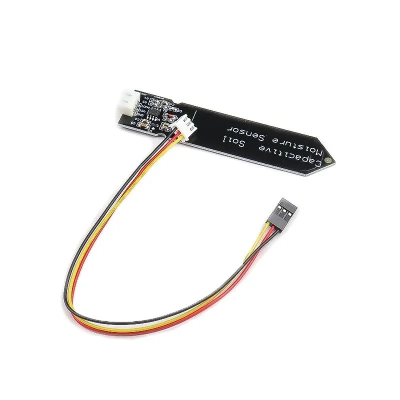
Capacitive Soil Moisture Sensor
Corrosion-resistant capacitive design — far more durable than resistive sensors. Requires dry/wet calibration before use for accurate soil moisture percentage readings.
8. Calibrating Current Sensors (ACS712, INA219)
ACS712 Calibration
The ACS712 outputs 2.5V at zero current, with a sensitivity of 66 mV/A (30A version), 100 mV/A (20A), or 185 mV/A (5A). Calibration steps:
- Zero calibration: With no current flowing, read the ADC value. This is your zero-current baseline. It should be near 512 (10-bit, 5V), but may differ due to supply voltage variations.
- Calculate actual voltage:
vZero = (adcZero / 1023.0) * 5.0; - For live current:
current = (vSensor - vZero) / sensitivity; - Verify with a known load (e.g., a resistor with known resistance and measured voltage).

5A Range Current Sensor Module ACS712
Hall-effect current sensor with 185mV/A sensitivity. Perform zero-current calibration at startup for accurate bidirectional current measurement.
INA219 Calibration
The INA219 uses a shunt resistor and internal calibration registers. The library handles most of this, but you need to set the correct shunt resistance value. If your shunt is not exactly the specified value (measure it with a multimeter), update the library initialization accordingly.
9. Implementing Calibration in Arduino Code
Here is a clean, reusable calibration implementation pattern:
// Calibration coefficients (set these from your calibration run)
struct CalibrationData {
  float offset; // additive correction
  float gain;   // multiplicative correction
};

CalibrationData tempCal = {-1.5, 1.02}; // example values

float applyCalibration(float rawValue, CalibrationData cal) {
  return (rawValue + cal.offset) * cal.gain;
}

void loop() {
  float rawTemp = readRawTemperature();
  float calibratedTemp = applyCalibration(rawTemp, tempCal);
  Serial.println(calibratedTemp);
}
10. Storing Calibration Values in EEPROM
Hard-coding calibration values is fine for a fixed installation, but for a product or a sensor you plan to re-calibrate periodically, store them in EEPROM so they survive power cycles:
#include <EEPROM.h>

void saveCalibration(float offset, float gain) {
  EEPROM.put(0, offset); // stores 4 bytes at address 0
  EEPROM.put(4, gain);   // stores 4 bytes at address 4
}

void loadCalibration(float &offset, float &gain) {
  EEPROM.get(0, offset);
  EEPROM.get(4, gain);
  // Validate: check for NaN or extreme values
  if (isnan(offset) || abs(offset) > 100) offset = 0.0;
  if (isnan(gain) || gain < 0.5 || gain > 2.0) gain = 1.0;
}
For ESP32, use the Preferences library instead of EEPROM for more reliable flash storage.
11. Best Practices and Common Mistakes
Best Practices
- Warm up your sensor before calibrating — most sensors need 2–5 minutes to stabilize thermally.
- Calibrate at operating temperature — sensor characteristics change with temperature, so calibrate in the environment where the sensor will be used.
- Use stable references — an ice-water bath is more stable than a frozen ice cube. Boiling water at your altitude is more reproducible than a random high-temperature oven.
- Average multiple readings — take 50–100 readings and average them to reduce noise during calibration.
- Document everything — write down the date, reference values, raw readings, and computed coefficients for each sensor unit.
- Re-calibrate periodically — sensors drift over time. Recalibrate every 6–12 months for critical applications.
Common Mistakes
- Calibrating with only one reference point — this only corrects offset, not gain.
- Using an uncalibrated reference — if your “reference” thermometer is also off, you are calibrating against a wrong value.
- Ignoring sensor warm-up time — early readings are unreliable.
- Not checking for temperature coefficient — some sensors drift more at extreme temperatures.
- Forgetting to save calibration values — they disappear on power cycle without EEPROM storage.
FAQ: Sensor Calibration
How often should I calibrate my Arduino sensors?
For non-critical hobby projects, calibrate once and you are done. For smart agriculture, weather stations, or safety-critical systems, recalibrate every 6–12 months. Gas sensors (MQ series) drift faster and may need recalibration every 3–6 months. Always recalibrate after a sensor has been stored for a long time or exposed to extreme conditions.
Can I calibrate a DHT11 sensor?
Yes, but with limitations. The DHT11 has a ±2°C / ±5%RH accuracy, which means individual units can vary widely. You can apply an offset correction by comparing against a known reference. However, for applications requiring better than ±1°C accuracy, consider upgrading to DHT20, DS18B20, or BME280 instead of trying to calibrate a DHT11.
What is a two-point calibration and when do I need it?
Two-point calibration uses two known reference values to correct both offset error and gain error. You need it when your sensor does not read linearly — for example, if it reads 1°C low at 0°C but 3°C low at 100°C. This indicates a gain error that a single-point (offset-only) calibration cannot fix. Any time your sensor covers a wide range and accuracy matters throughout that range, use two-point calibration.
My sensor readings fluctuate even after calibration — what should I do?
Fluctuating readings after calibration are a noise problem, not a calibration problem. Calibration corrects systematic (consistent) errors; noise is random. Solutions include: adding a decoupling capacitor (100nF) between VCC and GND close to the sensor, using averaging/median filtering in code, shielding sensor wires, or switching to a sensor with built-in digital filtering (like the DHT20 or DS18B20). See our guide on fixing noisy sensor readings for detailed techniques.
Do I need special equipment to calibrate sensors?
Not for most hobby sensors. Ice water (0°C) and boiling water (100°C) are free and accurate temperature references. A good digital thermometer (even a ₹200 cooking thermometer) works as a reference for mid-range temperatures. For humidity, saturated salt solutions are the standard low-cost reference. For current sensors, use a known resistor load and a basic multimeter. Professional labs use NIST-traceable standards, but for Arduino projects, these DIY references give you plenty of accuracy.
Ready to Build Calibrated Sensor Projects?
Accurate sensor data is the foundation of every reliable IoT, automation, and smart agriculture project. Whether you are calibrating a simple LM35 temperature sensor or a complex multi-sensor environmental monitoring system, the techniques in this guide will help you get readings you can trust.
Browse Zbotic’s full range of sensors — from temperature and humidity to soil moisture, current, and pressure — all ready to be calibrated and deployed in your next project.


Add comment