
How to Wire LEDs in Series vs Parallel: Calculations
Understanding how to wire LEDs in series vs parallel is one of the most fundamental skills in electronics. Whether you’re building a decorative light strip, adding indicators to a project, or creating a custom LED panel, the wiring configuration you choose determines brightness, power consumption, and overall reliability. This guide breaks down both methods with clear calculations, so even a complete beginner can confidently wire LEDs for any project. We’ll also cover resistor selection — the most common point of confusion for Indian hobbyists.
LED Basics: Voltage and Current
Before comparing wiring methods, you need to understand two critical LED specifications:
- Forward Voltage (Vf): The voltage drop across an LED when it’s conducting. For a standard red LED, this is about 1.8V–2.2V. For blue, white, or green LEDs, it’s typically 3.0V–3.4V.
- Forward Current (If): The operating current for correct brightness. Most 5mm through-hole LEDs operate at 20mA. High-power LEDs may need 350mA or more.
LEDs are current-driven devices. Without a current-limiting resistor, they will draw as much current as the supply can provide and burn out almost immediately. The resistor is non-negotiable — never connect an LED directly to a supply without one.
Wiring LEDs in Series
In a series circuit, all LEDs are connected end-to-end in a single chain. The same current flows through every LED, and the total voltage drop is the sum of all individual LED forward voltages.
Series Circuit Rules
- Current: Same through all LEDs (If remains constant)
- Voltage: Total supply voltage = sum of all LED Vf + resistor voltage drop
- Failure mode: If one LED fails (opens), all LEDs go dark
Series Example Calculation
Suppose you want to wire 3 red LEDs (Vf = 2V each) in series from a 12V supply, with a target current of 20mA:
- Total LED voltage drop = 3 × 2V = 6V
- Remaining voltage for resistor = 12V − 6V = 6V
- Resistor value = V ÷ I = 6V ÷ 0.02A = 300Ω
- Nearest standard value: 330Ω
- Resistor power rating = V × I = 6V × 0.02A = 0.12W → use 0.25W carbon film resistor
Rule of thumb for series: Your supply voltage must be greater than the total sum of all LED forward voltages. With a 5V supply, you can only run one white LED (Vf ≈ 3.2V) in series before running out of headroom.
Wiring LEDs in Parallel
In a parallel circuit, all LEDs share the same voltage rails (positive and negative), but each LED has its own current path. Ideally, each LED also gets its own current-limiting resistor.
Parallel Circuit Rules
- Voltage: Same across all LEDs (Vf is the same for identical LEDs)
- Current: Total current = sum of individual LED currents
- Failure mode: If one LED fails, the others stay lit
Parallel Example Calculation
Wire 4 red LEDs (Vf = 2V) in parallel from a 5V supply, each at 20mA:
- Voltage drop across resistor = 5V − 2V = 3V (per LED)
- Resistor per LED = 3V ÷ 0.02A = 150Ω (use 150Ω or 180Ω)
- Total current from supply = 4 × 20mA = 80mA
Important: Always use individual resistors for each LED in a parallel configuration. A single shared resistor across all parallel LEDs causes uneven current distribution — LEDs with slightly lower Vf will draw more current and may burn out.

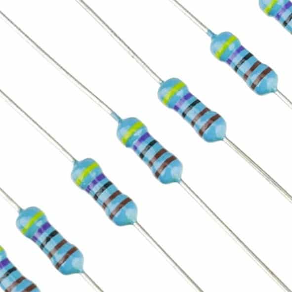
0 Ohm 0.25W Carbon Film Resistor (Pack of 100)
Stock up on carbon film resistors for your LED current-limiting needs. These 0.25W resistors are the go-to choice for 20mA LED circuits with standard forward voltages.
Series vs Parallel: When to Use Which
| Factor | Series | Parallel |
|---|---|---|
| Supply voltage needed | Must exceed sum of all Vf | Must exceed single LED Vf |
| Resistors required | One resistor for the chain | One per LED (recommended) |
| Brightness uniformity | Excellent (same current) | Good with individual resistors |
| Fault tolerance | Poor — one fail = all off | Good — others stay lit |
| Best for | High voltage supplies, uniform strips | Low-voltage logic systems, indicators |
| Total power draw | Lower (shared current) | Higher (current multiplied) |
Use series wiring when your supply voltage is high (12V, 24V) and you have multiple identical LEDs. Use parallel wiring when your supply is 3.3V or 5V (Arduino/Raspberry Pi GPIO pins) or when fault tolerance matters.
Resistor Calculations Made Simple
The universal LED resistor formula is:
R = (Vs − Vf) ÷ If
Where:
- Vs = Supply voltage (e.g., 5V, 9V, 12V)
- Vf = LED forward voltage (from datasheet, or 2V for red/yellow, 3.2V for blue/white)
- If = Desired forward current in amps (typically 0.02A = 20mA)
For series strings, replace Vf with the total forward voltage drop across all LEDs in the chain.
Quick Reference Table
| Supply | LED Type | LEDs in Series | Resistor (Ω) |
|---|---|---|---|
| 5V | Red (Vf=2V) | 1 | 150Ω |
| 5V | White (Vf=3.2V) | 1 | 82Ω–100Ω |
| 12V | Red (Vf=2V) | 3 | 300Ω (use 330Ω) |
| 12V | White (Vf=3.2V) | 3 | 120Ω (use 100Ω) |
| 3.3V (GPIO) | Red (Vf=2V) | 1 | 68Ω |
1.5 Ohm [0.25W] 1/4W Metal Film Resistor MFR (Pack of 100)
High-precision metal film resistors with tighter tolerances than carbon film, ideal for LED circuits where accurate current control matters for uniform brightness across parallel strings.
RGB LED Strips: Series or Parallel?
SMD LED strips (like the popular 5050 RGB or single-colour cold white strips) use a clever hybrid approach. Within each segment (usually 3 LEDs cut at the marked scissors line), the LEDs are wired in series. But each segment is wired in parallel with the rest of the strip. This is why:
- A 12V strip works because each 3-LED series segment uses 3 × Vf ≈ 9–10.5V, with a small resistor making up the rest.
- You can cut the strip at cut marks and it still works — each segment is independently parallel.
- A strip that goes dark in a patch means one or more series LEDs in that segment have failed.
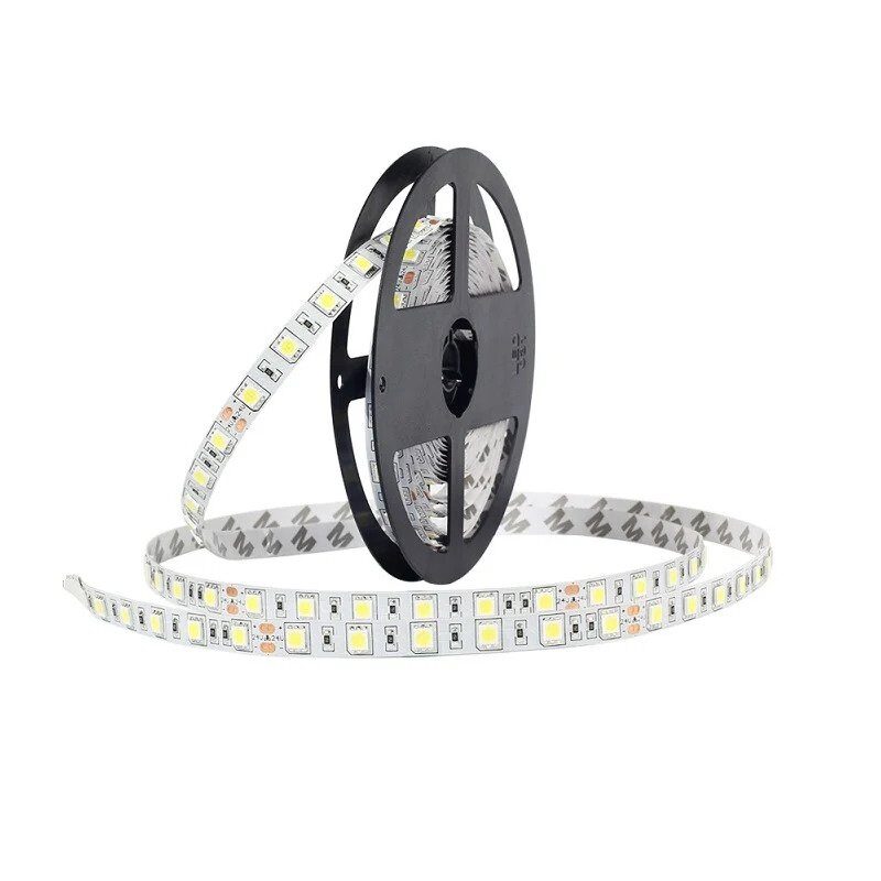
12V RGB 5050 SMD LED Strip – 5Meter
A premium 5-metre RGB LED strip using the 5050 SMD package. Each LED is a tri-colour RGB in one package. Perfect for understanding hybrid series-parallel wiring in real LED strips.
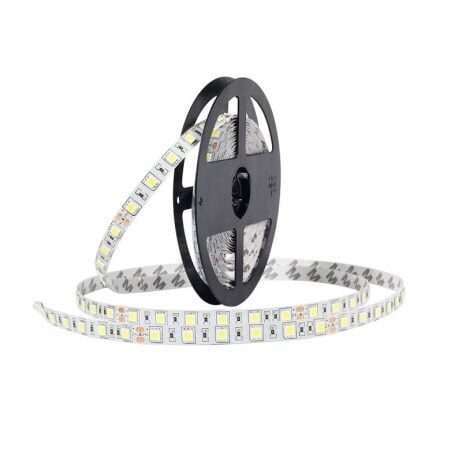
12V Cold White 5050 SMD LED Strip – 5Meter
Bright cool-white 5050 LED strip in a 5-metre roll. Uses 12V DC supply — pair with the 12V SMPS or 12V 2A adapter for a complete, ready-to-run lighting solution.
Practical Tips and Common Mistakes
- Always prototype on a breadboard: Use jumper wires to quickly test your circuit before soldering.
- Don’t mix LED colours in a single series string: Different Vf values mean different LEDs will be over- or under-driven.
- Use a multimeter: Measure actual current by placing the meter in series. Compare to your calculated value.
- Derate your resistor: If your calculation gives 0.12W, use a 0.25W resistor. If it gives 0.3W, use a 0.5W or 1W.
- Polarity matters: LEDs only conduct in one direction. The longer lead (anode) goes to positive. If an LED doesn’t light, try flipping it.
- PWM dimming works with both configurations: Connect a PWM signal (from Arduino) to the gate of a MOSFET driving the LED string for smooth dimming.
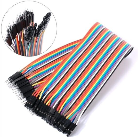
10CM Male To Female Breadboard Jumper Wires 2.54MM – 40Pcs
Essential for breadboard prototyping your LED circuits. Connect Arduino GPIO pins (female socket) to breadboard rows for quick and reliable LED wiring experiments.
Frequently Asked Questions
Q: Can I connect LEDs directly to a 5V Arduino pin without a resistor?
No. Even though Arduino pins are current-limited to about 40mA, a typical red LED (Vf=2V) without a resistor will pull maximum current, potentially damaging the LED and the GPIO pin. Always use a resistor — a 150Ω resistor limits current to about 20mA from a 5V pin.
Q: How many LEDs can I run in parallel from a single Arduino pin?
Each Arduino GPIO pin can source or sink a maximum of 40mA, and the total across all pins is 200mA. For 20mA LEDs, run a maximum of 2 per pin (with individual resistors). For more, use a transistor or MOSFET as a driver.
Q: What happens if one LED in a series string burns out?
If the failed LED acts as an open circuit, the entire string goes dark. If it short-circuits, the remaining LEDs receive more current and may burn out one by one. This is the main disadvantage of series wiring for reliability.
Q: Why do my parallel LEDs have different brightness levels?
LEDs from the same batch have slightly different forward voltages. Without individual resistors, the LED with the lowest Vf draws the most current and appears brightest. Add individual current-limiting resistors to each LED to equalise brightness.
Q: Should I use series or parallel for a 12V car LED circuit?
For 12V automotive applications, 3 red LEDs in series with a single 150Ω resistor is a clean solution. This is efficient (minimum wasted voltage across the resistor) and bright. Avoid single-LED parallel strings from 12V as most of the power is wasted in the resistor.
Build Your LED Projects with Quality Components
From individual LEDs and resistors to full 5-metre RGB strips and controllers, Zbotic.in has everything you need for your lighting projects. Shop online with fast delivery across India and get genuine components every time.


Add comment