
Noise pollution is an increasingly serious concern in urban environments, industrial workplaces, schools, and recording studios. Building a noise level sensor with Arduino gives you a cost-effective, DIY decibel meter capable of monitoring ambient sound, triggering alerts when thresholds are exceeded, and logging data over time. This tutorial covers everything you need — from understanding how sound sensors work to writing production-quality Arduino code for real-world noise monitoring applications.
What Is a Noise Level Sensor?
A noise level sensor is an electronic module that converts sound pressure waves in the air into electrical signals that a microcontroller can read and process. When paired with an Arduino and some math, it can approximate sound pressure levels in decibels (dB), detect claps or loud events, measure continuous ambient noise, and trigger responses like LEDs, buzzers, relays, or cloud alerts.
Noise level sensors are widely used in:
- Smart home automation (clap-to-switch lights)
- Industrial noise monitoring for worker safety compliance
- Classroom or library quiet monitors
- Recording studio acoustic measurement
- Environmental monitoring stations
- Baby monitors with cry detection
How Sound Sensor Modules Work
Most Arduino-compatible sound sensor modules are built around a small electret microphone combined with an amplifier circuit (typically based on the LM393 comparator or an LM386 op-amp). Here is the signal chain:
- Microphone: Converts sound pressure waves into a tiny AC voltage signal (usually in the millivolt range).
- Amplifier: Boosts the weak microphone signal to a usable level. Many modules have a potentiometer to adjust gain.
- Comparator (LM393): Compares the amplified signal against a threshold voltage set by an onboard potentiometer. Outputs a HIGH/LOW digital signal (DO pin) when sound exceeds the threshold.
- Analog output (AO pin): Provides a continuous analog voltage proportional to the sound level, readable by Arduino’s ADC.
The DO (digital output) pin is useful for simple event detection (clap, knock, voice activation). The AO (analog output) pin is required for measuring actual sound levels and approximating decibels.
Common Sound Sensor Modules Compared
Several modules are popular in the maker community:
- KY-038 / KY-037: Basic microphone modules with LM393 comparator. Very affordable, good for clap detection and threshold alerts. Limited dynamic range for precise dB measurement.
- MAX4466 Microphone Amplifier: Adjustable gain (25x to 125x), very low noise floor, excellent for audio frequency measurements and more precise SPL estimation.
- MAX9814 Auto Gain Control Mic: Automatically adjusts gain, good for varying sound environments. Easier to use but less fine-grained control.
- INMP441 I2S MEMS Microphone: Digital I2S output, very high SNR, used with ESP32 for professional-grade sound level measurements.
For this tutorial, we use the popular KY-038/KY-037 style module since it is the most widely available, and we will also show the MAX4466 approach for better accuracy.
Understanding Decibels
Decibels (dB) are a logarithmic unit of measurement for sound pressure level (SPL). The logarithmic scale is used because human hearing spans an enormous dynamic range — from the threshold of hearing (0 dB SPL) to the threshold of pain (~130 dB SPL). Common reference points:
- 0 dB: Threshold of hearing
- 30 dB: Quiet library, whisper at 2 metres
- 60 dB: Normal conversation at 1 metre
- 85 dB: OSHA workplace noise action level (damage possible with prolonged exposure)
- 100 dB: Motorcycle engine at 25 metres
- 120 dB: Concert near speakers — immediate danger
Important note on Arduino-based dB measurement: Consumer electret microphones are not calibrated laboratory instruments. An Arduino-based noise meter gives you relative noise levels and approximate SPL, not traceable laboratory accuracy. For calibrated measurements, cross-reference with a smartphone SPL meter app (which is also uncalibrated but typically better than a bare electret mic).
Wiring the Sound Sensor to Arduino
For a KY-038 or KY-037 module with both digital and analog outputs:
- VCC → Arduino 5V
- GND → Arduino GND
- DO (Digital Out) → Arduino digital pin D2 (with interrupt support)
- AO (Analog Out) → Arduino analog pin A0
Additionally, for a visual noise level display, connect:
- 3× LEDs (green, yellow, red) with 220 Ω resistors to pins D10, D11, D12
- Optional: 16×2 I2C LCD display (SDA→A4, SCL→A5)
Potentiometer adjustment: The blue potentiometer on the module adjusts the DO trigger threshold. Turn it clockwise to increase sensitivity (trigger on quieter sounds) or anticlockwise to decrease it.
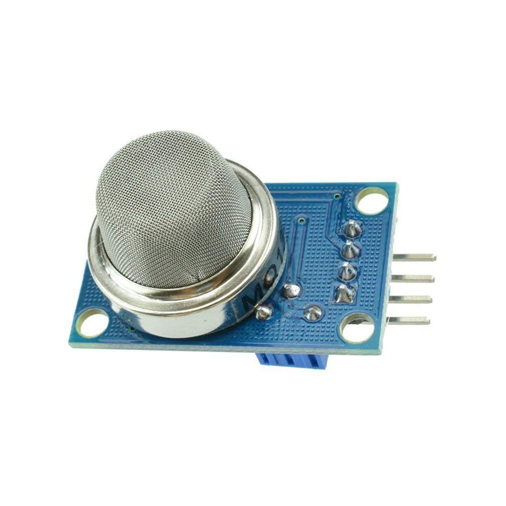
MQ-135 Air Quality/Gas Detector Sensor
Build a comprehensive environmental monitor by pairing your noise level sensor with this gas quality sensor for a full indoor air and noise quality station.
Basic Noise Detection Code
Start with a simple sketch that reads both digital and analog outputs and prints them to Serial Monitor:
// Noise Level Sensor - Basic Reading
// Zbotic.in - Sensors & Measurement Tutorial

const int SOUND_DO_PIN = 2;   // Digital output from sound module
const int SOUND_AO_PIN = A0;  // Analog output from sound module

// LED pins for noise level indicator
const int LED_GREEN  = 10;  // Quiet
const int LED_YELLOW = 11;  // Moderate
const int LED_RED    = 12;  // Loud

void setup() {
  Serial.begin(9600);
  pinMode(SOUND_DO_PIN, INPUT);
  pinMode(LED_GREEN,  OUTPUT);
  pinMode(LED_YELLOW, OUTPUT);
  pinMode(LED_RED,    OUTPUT);
  Serial.println("Noise Level Sensor Ready");
}

void loop() {
  int digitalVal = digitalRead(SOUND_DO_PIN);
  int analogVal  = analogRead(SOUND_AO_PIN);

  Serial.print("Digital: ");
  Serial.print(digitalVal == HIGH ? "LOUD" : "quiet");
  Serial.print(" | Analog: ");
  Serial.println(analogVal);

  // Update LED noise level indicator
  if (analogVal < 300) {
    digitalWrite(LED_GREEN,  HIGH);
    digitalWrite(LED_YELLOW, LOW);
    digitalWrite(LED_RED,    LOW);
  } else if (analogVal < 600) {
    digitalWrite(LED_GREEN,  HIGH);
    digitalWrite(LED_YELLOW, HIGH);
    digitalWrite(LED_RED,    LOW);
  } else {
    digitalWrite(LED_GREEN,  HIGH);
    digitalWrite(LED_YELLOW, HIGH);
    digitalWrite(LED_RED,    HIGH);
  }

  delay(50);
}
Measuring Approximate Decibels
To get a dB approximation from the raw ADC reading, we use a logarithmic conversion. The analog value represents sound pressure (linear scale), and decibels are a log10-based scale. Here is a more advanced sketch:
// Noise Level Sensor - Approximate dB Measurement
// Zbotic.in - Sensors & Measurement Tutorial

const int SOUND_PIN = A0;
const int SAMPLE_COUNT = 128;  // Samples for RMS calculation

// Calibration: adjust VREF_DB to match a reference SPL meter
// Start with 50.0 and adjust ±10 dB to match reality
const float VREF_DB = 50.0;

float readSoundLevel() {
  long sumSquares = 0;
  int baseline = 512; // Midpoint of 10-bit ADC (2.5V on 5V system)

  for (int i = 0; i < SAMPLE_COUNT; i++) {
    int reading = analogRead(SOUND_PIN) - baseline;
    sumSquares += (long)reading * reading;
    delayMicroseconds(125); // ~8kHz sampling rate
  }

  float rms = sqrt((float)sumSquares / SAMPLE_COUNT);

  // Convert RMS ADC value to approximate dB SPL
  // dB = 20 * log10(rms / reference) + calibration_offset
  if (rms < 1.0) rms = 1.0; // Avoid log(0)
  float dB = 20.0 * log10(rms) + VREF_DB;
  return dB;
}

void setup() {
  Serial.begin(9600);
  Serial.println("Noise Level dB Meter");
}

void loop() {
  float soundLevel = readSoundLevel();

  Serial.print("Sound Level: ");
  Serial.print(soundLevel, 1);
  Serial.println(" dB");

  // Noise classification
  if      (soundLevel < 40)  Serial.println(" → Very Quiet");
  else if (soundLevel < 55)  Serial.println(" → Quiet");
  else if (soundLevel < 70)  Serial.println(" → Moderate");
  else if (soundLevel < 85)  Serial.println(" → Loud");
  else                       Serial.println(" → Very Loud - Warning!");

  delay(500);
}
The RMS (Root Mean Square) calculation is important for sound measurement because sound waves are AC signals. RMS represents the effective power level of the sound, analogous to how we measure AC mains voltage as RMS rather than peak.
Data Logging with SD Card
For continuous noise monitoring, log readings to an SD card with timestamps. Add an SD card module (SPI) and an RTC module (DS1307 or DS3231 via I2C):
#include <SD.h>
#include <RTClib.h>

RTC_DS3231 rtc;
File logFile;
const int SD_CS_PIN = 10;

void setup() {
  Serial.begin(9600);
  Wire.begin();
  rtc.begin();
  SD.begin(SD_CS_PIN);
  logFile = SD.open("noise_log.csv", FILE_WRITE);
  if (logFile) logFile.println("Timestamp,dB_Level,Classification");
}

void loop() {
  float level = readSoundLevel(); // From previous sketch
  DateTime now = rtc.now();
  String timestamp = String(now.year()) + "-" +
                     String(now.month()) + "-" +
                     String(now.day()) + " " +
                     String(now.hour()) + ":" +
                     String(now.minute()) + ":" +
                     String(now.second());

  String line = timestamp + "," + String(level, 1) + "," +
                (level > 85 ? "ALERT" : "OK");

  if (logFile) { logFile.println(line); logFile.flush(); }
  Serial.println(line);
  delay(1000);
}
Building a Noise Alert System
A practical noise alert system for a classroom or office can use the following logic:
- Baseline learning: On startup, measure ambient noise for 30 seconds to establish a baseline. Set alert threshold at baseline + 15 dB.
- Sustained noise detection: Only alert if noise exceeds the threshold for more than 3 consecutive seconds (avoids false triggers from single claps or door slams).
- Visual alert: Red LED or NeoPixel strip turns on when noise threshold is exceeded.
- Audible alert: Passive buzzer sounds a short tone.
- WiFi alert: With an ESP8266/ESP32, send push notifications via Telegram Bot API or email when sustained noise is detected.
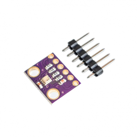
GY-BME280-3.3 Atmospheric Pressure Sensor
Combine with a noise sensor for a full environmental monitoring station measuring temperature, humidity, pressure, and sound levels together.
Real-World Project Ideas
- Smart classroom noise monitor: Display a traffic-light LED bar on the classroom wall. When noise exceeds 70 dB for 5+ seconds, the red light activates and a countdown timer starts before the teacher is alerted.
- Workplace safety monitor: Log hourly average noise levels to comply with OSHA/IS 3483 noise exposure standards. Export CSV data for safety reports.
- Clap light switch: Detect a double-clap pattern (two sounds within 500ms) to toggle a relay controlling room lights — a classic, fun project.
- Music reactive lights: Drive a WS2812B NeoPixel strip with brightness proportional to sound level for music-reactive ambient lighting.
- Snoring detector: Place near a bed; log high-noise events during sleep hours to analyse snoring patterns.
- Construction site monitor: Battery-powered Arduino + ESP8266 + solar panel, logging noise data to a cloud dashboard (Thingspeak, Grafana).
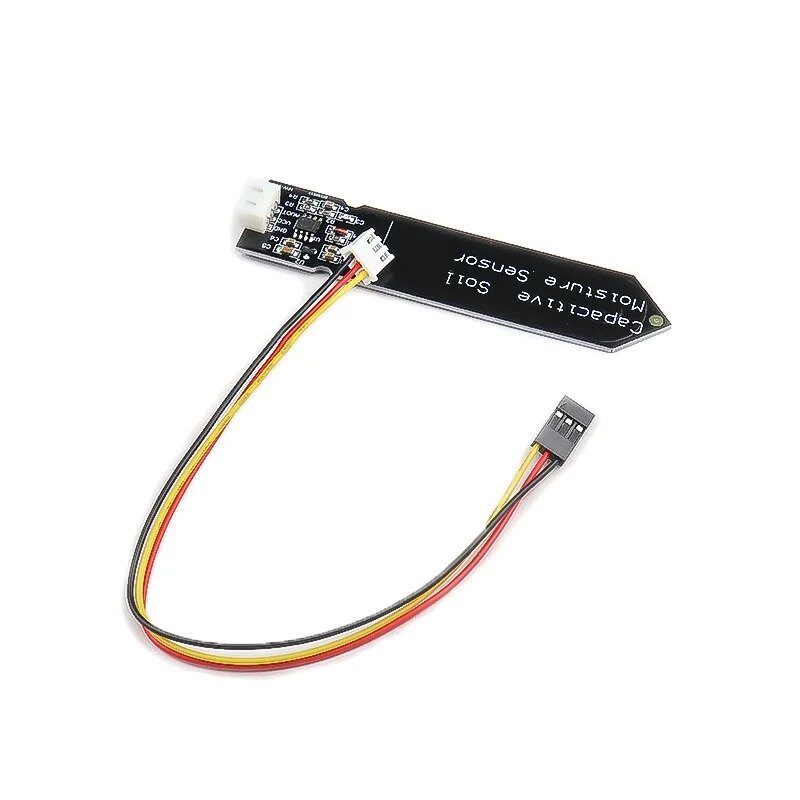
Capacitive Soil Moisture Sensor
Extend your environmental monitoring station to include soil moisture data for a complete IoT garden or greenhouse monitoring solution.
Frequently Asked Questions
How accurate is an Arduino noise level sensor in dB?
A consumer electret microphone module with an Arduino can approximate sound levels to within ±5 to ±10 dB after calibration against a reference meter. The readings are useful for relative comparisons and threshold detection but should not be used for regulatory compliance measurements that require certified Class 1 or Class 2 sound level meters.
What is the difference between the DO and AO pins on a sound module?
DO (Digital Output) is a binary signal — HIGH when sound exceeds the threshold set by the onboard potentiometer, LOW otherwise. AO (Analog Output) provides a continuous voltage proportional to the sound level, allowing you to measure relative sound intensity and calculate approximate decibel values using the ADC.
Why does my noise sensor give unstable readings?
Instability is usually caused by electrical noise on the power supply. Use a 100µF electrolytic capacitor across VCC and GND near the module. Also, use the RMS averaging method in your code (average many samples) instead of reading a single sample. Keep sensor wires short and away from PWM output pins or motor drivers.
Can I use a noise sensor with an ESP8266 or ESP32?
Yes, with a note: ESP8266 has only one ADC pin (A0) limited to 1V input. Use a voltage divider to scale the sensor output. ESP32 has multiple 12-bit ADC pins and is the better choice, offering higher resolution and Wi-Fi for cloud logging. The INMP441 I2S digital microphone is the best option for ESP32-based projects.
How do I calibrate my Arduino sound sensor to match dB SPL values?
Use a free SPL meter app on your smartphone as a reference. Play a consistent tone (sine wave at 1kHz) at a known volume, measure with both the app and your Arduino setup, and adjust the VREF_DB calibration constant until the readings match. Recalibrate if you change the microphone module or adjust the gain potentiometer.
Start Your Noise Monitoring Project Today
Find all the sensors, modules, and components you need for your Arduino noise level meter at Zbotic.in. Fast delivery across India, expert support, and competitive prices on all maker electronics.


Add comment