
When browsing for a small OLED display for your next Arduino or ESP32 project, you’ll almost always come down to two choices: the 0.96 inch OLED and the 1.3 inch OLED. They look similar, cost roughly the same, and both use I2C. But the differences matter more than you’d think — especially when it comes to driver chips, library compatibility, and legibility. This 0.96 vs 1.3 inch OLED display comparison will help you pick the right module for your specific project so you don’t end up ordering the wrong one and waiting another week for delivery.
Quick Comparison: At a Glance
| Feature | 0.96 inch OLED | 1.3 inch OLED |
|---|---|---|
| Screen Size | 0.96″ diagonal | 1.3″ diagonal |
| Resolution | 128 × 64 pixels | 128 × 64 pixels |
| Common Driver | SSD1306 | SH1106 (mostly) |
| Interface | I2C or SPI | I2C or SPI |
| Operating Voltage | 3.3V / 5V | 3.3V / 5V |
| Current Draw | ~20mA typical | ~25mA typical |
| Pixel Density | ~132 PPI (very dense) | ~100 PPI |
| Text Legibility | Good with small fonts | Better for larger text |
| PCB Size | Smaller, compact | Slightly larger |
| Best For | Wearables, small enclosures | Standalone gadgets, dashboards |
How OLED Displays Work
OLED stands for Organic Light-Emitting Diode. Unlike LCD displays that require a backlight, each pixel in an OLED display generates its own light. This produces true blacks (pixels simply switch off), excellent contrast ratios, and — critically for battery-powered projects — power consumption proportional to what’s displayed. A screen showing mostly black draws far less power than one with white backgrounds.
Both the 0.96″ and 1.3″ modules use monochrome OLED panels (white, blue, or yellow-blue bicolor variants). The monochrome variants are simpler to drive and far cheaper than color OLED, making them perfect for data display overlays, status panels, and compact instrument clusters.
The modules communicate via I2C (just 2 wires: SDA + SCL) or SPI (4 wires, faster refresh). Most hobbyist modules default to I2C with address 0x3C (or 0x3D if the address jumper is bridged).
0.96 Inch OLED — Features & Best Uses
The 0.96″ OLED is the most popular OLED module in the Arduino community. Its small size, extremely wide library support, and affordable price (typically ₹80–120 in India) make it the default choice for quick projects.
Strengths:
- Compact footprint — fits inside small enclosures, behind bezels, or on a breadboard without dominating space
- Universal library support — Adafruit SSD1306 library works out of the box, no configuration needed
- Low power — typically 20mA active, making it viable for battery-powered wearables
- High pixel density — at 132 PPI, small text and icons look crisp up close
- Wide availability — easiest to source in India with consistent quality
Limitations:
- The physical size means text and icons look small from more than 30–40cm viewing distance
- Not ideal when you need to show data to someone standing nearby
Best project applications: Wearable fitness trackers, smart watch faces, compact weather stations inside small boxes, status displays on robotics, USB-C power meter displays, and anywhere size is more important than legibility at a distance.
1.3 Inch OLED — Features & Best Uses
The 1.3″ OLED module is the step-up sibling offering noticeably more screen real estate. Same 128×64 resolution but spread over a larger physical area — each pixel is about 35% larger, making text and graphics much easier to read at arm’s length.
Strengths:
- Better legibility — text is comfortable to read from 50–80cm without squinting
- Same resolution — all your existing graphics code works, just displayed larger
- Dashboard-friendly — works well as a standalone instrument panel visible across a workbench
- Good for demos — when showing a project to others, the larger display is far more impressive
Limitations:
- Uses SH1106 driver on most modules — requires a different library or explicit driver selection
- Slightly larger PCB footprint — may not fit compact enclosures
- Less common than 0.96″, so may have more vendor variation
Best project applications: Desktop weather stations, lab instrument readouts, retro clock projects with large digits, Raspberry Pi status displays, workshop tool monitors, and any standalone gadget displayed on a shelf or desk.
Driver Chips: SSD1306 vs SH1106
This is the most important technical difference between the two modules and the most common source of confusion:
The SSD1306 (common in 0.96″ modules) has a 128×64 pixel frame buffer that maps directly to the display. Commands address columns 0–127 and pages 0–7 directly. The Adafruit SSD1306 library talks to it natively.
The SH1106 (common in 1.3″ modules) has a slightly larger 132×64 internal frame buffer. It supports page addressing but uses a 2-pixel offset, meaning commands to column 0 actually write to pixel column 2 of the internal buffer. If you use the SSD1306 library unchanged, you’ll see the display content shifted 2 pixels horizontally or see artifacts at the screen edges.
Fix for 1.3″ SH1106: Use a library that explicitly supports SH1106:
- U8g2 library — supports both SSD1306 and SH1106; change the constructor to
U8G2_SH1106_128X64_NONAME_F_HW_I2C - Adafruit SH110x library — Adafruit’s dedicated SH1106/SH1107 library
- u8x8 library — text-only, ultra-low memory, supports both chips
Note: Some 1.3″ modules actually do use SSD1306 — check the product listing or read the markings on the driver IC with a magnifier. When in doubt, try the SSD1306 library first; if the image is offset, switch to SH1106.
Wiring & Library Compatibility
Wiring is identical for both modules in I2C mode:
| OLED Pin | Arduino Uno | ESP32 |
|---|---|---|
| VCC | 3.3V or 5V | 3.3V |
| GND | GND | GND |
| SDA | A4 | GPIO21 |
| SCL | A5 | GPIO22 |
Basic code for the 0.96″ (SSD1306) using Adafruit library:
#include <Wire.h>
#include <Adafruit_GFX.h>
#include <Adafruit_SSD1306.h>

Adafruit_SSD1306 display(128, 64, &Wire, -1);

void setup() {
  display.begin(SSD1306_SWITCHCAPVCC, 0x3C);
  display.clearDisplay();
  display.setTextSize(2);
  display.setTextColor(WHITE);
  display.setCursor(10, 20);
  display.println("Zbotic!");
  display.display();
}
For the 1.3″ (SH1106) using U8g2:
#include <U8g2lib.h>
#include <Wire.h>

U8G2_SH1106_128X64_NONAME_F_HW_I2C u8g2(U8G2_R0, U8X8_PIN_NONE);

void setup() {
  u8g2.begin();
  u8g2.clearBuffer();
  u8g2.setFont(u8g2_font_ncenB14_tr);
  u8g2.drawStr(10, 40, "Zbotic!");
  u8g2.sendBuffer();
}
Recommended Products from Zbotic
Pair either OLED with these popular sensors for complete projects:
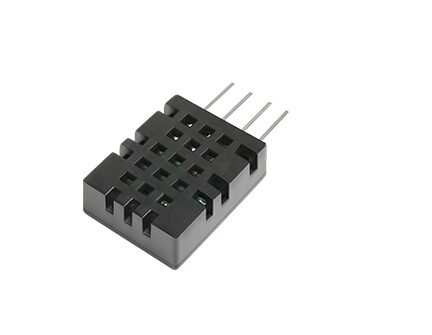
DHT20 SIP Packaged Temperature and Humidity Sensor
I2C temperature and humidity sensor — ideal companion for an OLED display project. Display live T&H readings in big text on either the 0.96″ or 1.3″ module.
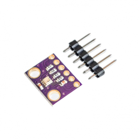
GY-BME280-3.3 Precision Altimeter Atmospheric Pressure Sensor Module
Combine with a 1.3″ OLED for a full weather station displaying temperature, humidity, pressure, and altitude — four values in a clean four-line layout.

DS18B20 Programmable Resolution Temperature Sensor
High-accuracy 1-Wire temperature sensor — display precise readings up to ±0.5°C on your OLED. Great for sous vide controllers, incubator monitors, and aquarium thermometers.
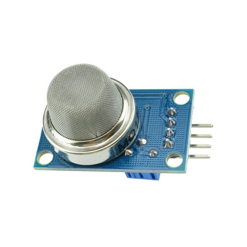
MQ-135 Air Quality/Gas Detector Sensor Module for Arduino
Build an indoor air quality monitor — display CO2, ammonia, and benzene levels on your OLED with a scrolling bar graph. The 1.3″ OLED shows the graph more clearly.
Frequently Asked Questions
Which OLED is better for Arduino beginners?
The 0.96 inch OLED with SSD1306 driver is better for beginners. The Adafruit SSD1306 library is the most documented, has the most tutorials, and just works. You can find working code for nearly every sensor combination. If you choose the 1.3″ SH1106, add the U8g2 library to your toolkit and select the correct constructor.
Can I use multiple OLED displays on the same I2C bus?
Yes, with a limitation: each I2C device needs a unique address. Most OLED modules have address 0x3C, but many have a solder jumper to switch to 0x3D. This means you can run two OLEDs on one I2C bus (one at 0x3C, one at 0x3D). For more than two, use an I2C multiplexer like the TCA9548A, which gives you 8 independent I2C channels.
How long do OLED displays last?
OLED panels have finite lifetimes — typically 10,000–100,000 hours depending on brightness and usage patterns. Burn-in (static images permanently etched into the panel) is a real concern if you display the same content continuously at full brightness. Best practices: implement a screen saver (invert display or dim after 30 seconds of inactivity), reduce brightness, and rotate between display modes. For hobby projects that run a few hours a day, lifespan is not a practical concern.
What is the difference between white, blue, and yellow-blue bicolor OLED?
All are the same resolution and driver — only the emitting color differs. White is most versatile and readable in various lighting. Blue looks great in dark environments and has a retro aesthetic. Yellow-blue bicolor modules have the top 16 rows in yellow and remaining 48 rows in blue — useful for showing a title/label in yellow and data in blue, adding visual hierarchy without any extra code.
Do OLED displays work with 5V Arduino and 3.3V ESP32?
Yes — most OLED modules include a built-in voltage regulator and level shifter on the PCB, making them compatible with both 3.3V and 5V systems. The VCC pin typically accepts 3.3V–5V. However, the I2C lines (SDA/SCL) on some modules are not 5V tolerant — if you’re using a 5V Arduino, add 4.7kΩ pull-up resistors to 3.3V rather than 5V to be safe, or look for modules with onboard level shifting.
Shop display modules, sensors, and Arduino accessories at Zbotic.in — India’s trusted electronics store with delivery across all major cities.


Add comment