
Wireless Doorbell Project: 433MHz RF & Arduino DIY Guide
A wireless doorbell using 433MHz RF and Arduino is one of the most satisfying DIY electronics projects you can build — practical, useful at home, and a great way to learn about radio frequency communication. In this complete DIY guide, we’ll build a fully functional wireless doorbell where pressing a button at the door triggers a chime (or custom alert) anywhere in your house, without any wires between them. This project uses the popular 433MHz RF transmitter and receiver modules along with an Arduino board.
How 433MHz RF Communication Works
The 433.92 MHz ISM (Industrial, Scientific, Medical) band is one of the most widely used license-free radio frequencies in India and globally. The 433MHz RF modules you find at electronics stores use ASK (Amplitude Shift Keying) or OOK (On-Off Keying) modulation — the simplest form of digital radio transmission where the carrier wave is turned on and off to represent 1s and 0s.
The 433MHz transmitter module (TX) is a passive component — it only transmits when powered and given a serial data stream. The receiver module (RX) continuously listens and outputs the demodulated digital signal. Both operate at 5V (some at 3.3V), making them directly compatible with Arduino boards.
Key characteristics of 433MHz modules:
- Operating frequency: 433.92 MHz (license-free ISM band in India)
- Range: 20–100 metres in open air (with default PCB antenna)
- Data rate: typically 1–10 kbps
- Power: ~10mA receive, ~20–40mA transmit
- No protocol stack — raw bit transmission, so you handle encoding/decoding in software
For a doorbell, we only need to transmit a short unique code when the button is pressed. The receiver checks if the code matches and triggers the chime output. The RadioHead library for Arduino handles all the encoding, checksum, and reliable message delivery, making this project beginner-friendly.
Components You’ll Need
Transmitter side (outdoor button unit):
- Arduino Nano (or Pro Mini for smaller size)
- 433MHz RF Transmitter module (FS1000A or similar)
- Momentary push button
- 9V battery + battery clip (or 4xAA battery holder)
- Small project enclosure / waterproof box
- 17cm wire antenna (cut to quarter-wavelength)
Receiver side (indoor chime unit):
- Arduino Uno or Nano
- 433MHz RF Receiver module (XY-MK-5V or superheterodyne RXB6)
- Piezo buzzer or 5V active buzzer
- Optional: Relay module for controlling an existing doorbell chime or LED ring
- 5V USB power supply
- 17cm wire antenna
Total estimated cost: ₹300–₹600 for the complete project (basic version)
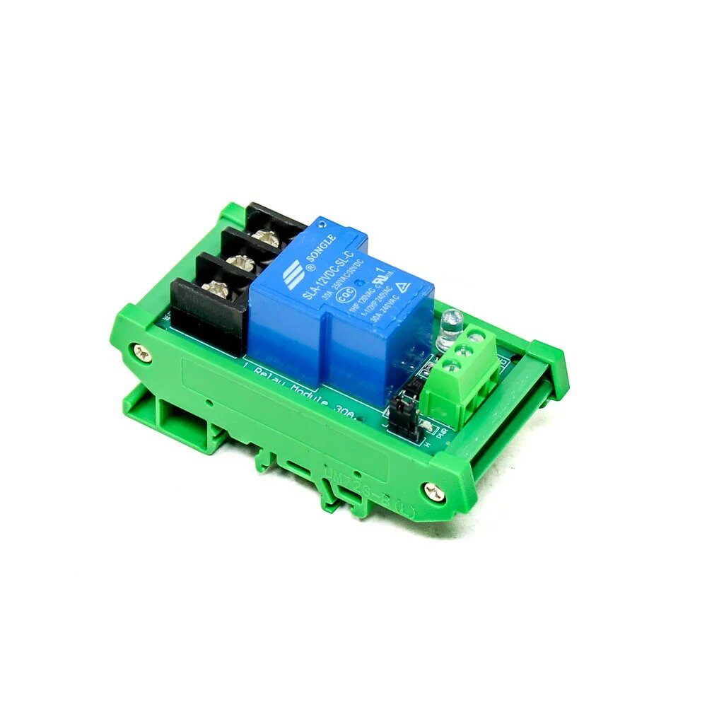
1 Channel 12V 30A Relay Module with Optocoupler
Use this relay module to interface your Arduino receiver with a conventional wired doorbell chime or buzzer. Optocoupler isolation protects your Arduino from high-voltage spikes.
Building the Transmitter Unit (Doorbell Button)
Wiring the transmitter:
- RF TX VCC → Arduino 5V
- RF TX GND → Arduino GND
- RF TX DATA → Arduino Digital Pin 12
- Push button: one leg to Arduino Digital Pin 2 (INPUT_PULLUP), other leg to GND
- Antenna: solder a 17.3cm straight wire to the ANT pin of the TX module
Power saving tip: Put the Arduino into deep sleep between button presses using the LowPower library with wake-on-interrupt on Pin 2 (the button pin). This can extend battery life from days to months, making the outdoor unit truly wireless for extended periods.
Building the Receiver Unit (Indoor Chime)
Wiring the receiver:
- RF RX VCC → Arduino 5V
- RF RX GND → Arduino GND
- RF RX DATA → Arduino Digital Pin 11
- Buzzer positive → Arduino Digital Pin 8
- Buzzer negative → GND
- Antenna: solder a 17.3cm wire to the ANT pin of the RX module
Superheterodyne vs superregenerative receivers: The cheap XY-MK-5V receiver is superregenerative — it works but is noisy and picks up interference easily. For a more reliable doorbell (especially in an environment with other 433MHz devices like remote-controlled fans, AC remotes, or security alarms), invest in a superheterodyne receiver like the RXB6 or RXB12. These cost slightly more but dramatically improve range and reduce false triggers.
1 Channel 12V Relay Module Solid State High Level SSR
Solid state relay for silent, long-life switching. Ideal for connecting the RF doorbell receiver to an existing AC-powered chime. No mechanical click — perfect for bedroom or office deployments.
Arduino Code for Transmitter and Receiver
Install the RadioHead library via Arduino IDE Library Manager (search “RadioHead” by Mike McCauley).
Transmitter Code (doorbell_tx.ino):
#include <RH_ASK.h>
#include <SPI.h>

RH_ASK driver(2000, 11, 12, 10); // speed, RX pin, TX pin, PTT pin

const int BUTTON_PIN = 2;
const char* DOORBELL_CODE = "ZBOTIC_BELL_001"; // Unique code

void setup() {
  pinMode(BUTTON_PIN, INPUT_PULLUP);
  driver.init();
}

void loop() {
  if (digitalRead(BUTTON_PIN) == LOW) {
    // Send doorbell code 3 times for reliability
    for (int i = 0; i < 3; i++) {
      driver.send((uint8_t*)DOORBELL_CODE, strlen(DOORBELL_CODE));
      driver.waitPacketSent();
      delay(50);
    }
    delay(1000); // Debounce - prevent multiple triggers
  }
}
Receiver Code (doorbell_rx.ino):
#include <RH_ASK.h>
#include <SPI.h>

RH_ASK driver(2000, 11, 12, 10);

const int BUZZER_PIN = 8;
const char* DOORBELL_CODE = "ZBOTIC_BELL_001"; // Must match TX code

void setup() {
  pinMode(BUZZER_PIN, OUTPUT);
  Serial.begin(9600);
  driver.init();
  Serial.println("Wireless Doorbell Receiver Ready");
}

void ringDoorbell() {
  for (int i = 0; i < 3; i++) {
    digitalWrite(BUZZER_PIN, HIGH);
    delay(200);
    digitalWrite(BUZZER_PIN, LOW);
    delay(150);
  }
}

void loop() {
  uint8_t buf[20];
  uint8_t buflen = sizeof(buf);

  if (driver.recv(buf, &buflen)) {
    buf[buflen] = ''; // Null terminate
    String received = String((char*)buf);

    Serial.print("Received: ");
    Serial.println(received);

    if (received == DOORBELL_CODE) {
      Serial.println("DOORBELL PRESSED!");
      ringDoorbell();
    }
  }
}
Testing: Upload the transmitter code to the TX Arduino and receiver code to the RX Arduino. Open Serial Monitor on the receiver at 9600 baud, press the button on the transmitter, and you should hear 3 beeps and see “DOORBELL PRESSED!” on the monitor.
Project Enhancements: Multiple Buttons and Zones
The basic doorbell works great, but here’s how to take it further:
Multiple door buttons: Simply use different DOORBELL_CODE strings for each button (e.g., “ZBOTIC_FRONT”, “ZBOTIC_BACK”, “ZBOTIC_GATE”). The receiver checks which code arrived and plays a different chime pattern or lights a different LED for each door. No additional hardware needed — just different codes.
Visual notification (great for hearing-impaired users): Add an LED strip or ring to the receiver. When the doorbell rings, flash the lights in addition to (or instead of) the buzzer. Use PWM to fade the LED in and out for a smoother effect.
Mobile notification via WiFi: Replace the receiver Arduino with an ESP8266 or ESP32. When the RF code is received, the ESP sends an HTTP request to a Telegram bot, WhatsApp (via Twilio), or a local MQTT broker. This way you get a phone notification even when you’re in the garden with headphones on.
Timestamp logging: Add an RTC (Real-Time Clock) module to the receiver Arduino and log every doorbell press with timestamp to an SD card. Know exactly when someone rang your bell even when you weren’t home.
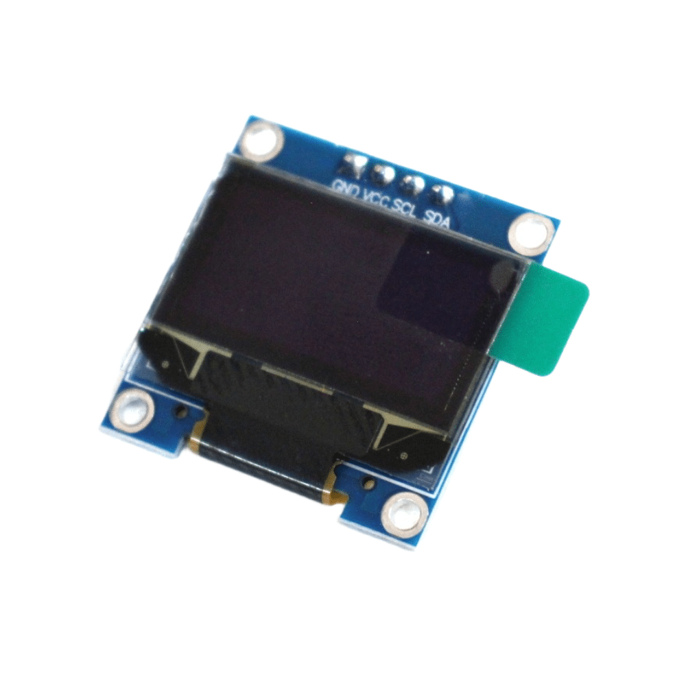
0.96 Inch I2C OLED LCD Module SSD1306
Add an OLED display to your receiver unit to show which door was pressed and the time of the last ring. Great for multi-button setups with front door, back door, and gate indicators.
Improving Range and Reliability
The default PCB trace antenna on cheap 433MHz modules gives 20–40 metres in open air. Here are proven techniques to improve range:
1. Wire antenna (17.3cm): Solder a straight 17.3cm wire to the ANT pad. This is a quarter-wavelength antenna at 433.92MHz and is the single biggest range improvement you can make. Range jumps to 50–100 metres typically.
2. Helical antenna: Wind 6–8 turns of 0.5mm copper wire around a 5mm former, with a total length of 17.3cm of wire. This gives better omnidirectional coverage in compact spaces.
3. Height matters: Mount the receiver antenna higher up, away from metal surfaces. 433MHz signals are absorbed by metal walls, water pipes, and reinforced concrete. In multi-story Indian homes with thick concrete walls, you may need a receiver extension antenna on the upper floor.
4. Increase TX power: Some RF transmitter modules support higher power (up to 100mW / 20dBm). Ensure your module’s specifications and check if the higher power version is available.
5. Use RH_ASK with higher speed: Slower data rates improve reception sensitivity. Try 1000 bps instead of 2000 bps in the RH_ASK constructor for better range at the cost of slightly slower transmission.
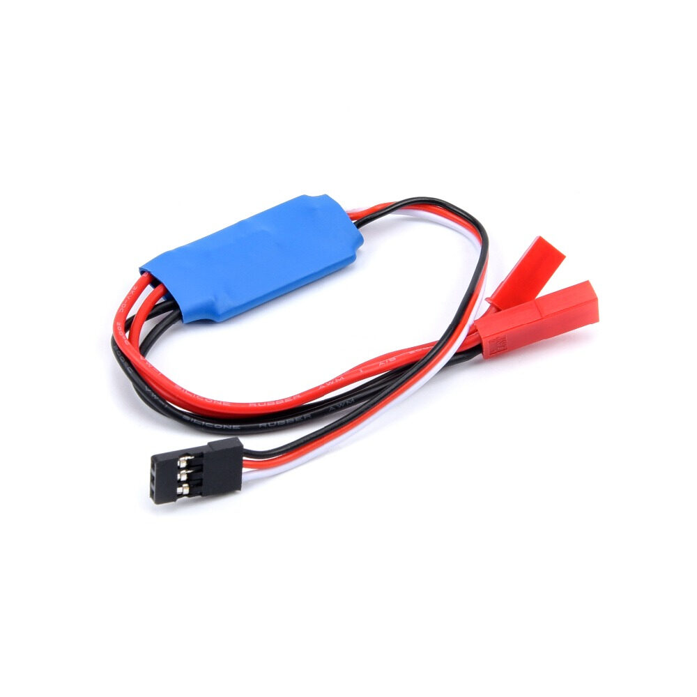
10A RC TX Controlled Relay Switch PWM Receiver
Ready-made RF receiver with built-in relay — use this as an alternative receiver unit for your wireless doorbell. No Arduino needed on the receiver side for the basic relay trigger function.
Frequently Asked Questions
Does a 433MHz RF module work without a library?
Yes, you can use simple digitalWrite to toggle the TX DATA pin and digitalRead on the RX DATA pin for basic bit-banged communication. However, the RadioHead library handles encoding, checksums, and noise filtering automatically, making it much more reliable for a real-world doorbell that must work every time without false triggers.
My 433MHz RF doorbell triggers randomly — what’s causing it?
Random triggers are caused by RF interference from other 433MHz devices (AC remote controls, ceiling fan remotes, security alarms, car key fobs, and wireless sensors all use this band). Solutions: (1) Use a longer, unique code (RadioHead sends checksum-verified packets); (2) Switch to a superheterodyne receiver (RXB6) instead of the cheap superregenerative module; (3) Add a software debounce that requires the same code to be received 2 times within 100ms before triggering.
How do I make the transmitter battery last longer?
Use Arduino sleep modes. With the LowPower library and Pin Change Interrupt on the button, the transmitter Arduino sleeps at ~5µA. It wakes only when the button is pressed, transmits the code (taking ~20ms), and goes back to sleep. A 9V battery can last 1–2 years with this approach, even if someone presses the button 10 times per day.
Can I use this project to control multiple devices from one button?
Yes — you can have multiple receiver units all listening for the same code. Each receiver can perform a different action (one rings a buzzer in the living room, another flashes lights in the bedroom, a third sends a WiFi notification). All receive the same RF transmission simultaneously since RF is broadcast.
What’s the range of 433MHz RF modules through concrete walls?
In typical Indian construction (6-inch RCC walls), each wall reduces range by approximately 50–70%. With a wire antenna and superheterodyne receiver, you can expect 15–25 metre range through 2–3 concrete walls. For a single-story home with one brick wall between door and indoor unit, the basic setup with wire antenna works reliably.
Build Your DIY Wireless Doorbell Today
Get relay modules, OLED displays, and all the components needed for your wireless doorbell project from Zbotic — India’s go-to electronics store for makers and hobbyists.


Add comment