
Whether you’re building a home weather station, monitoring wind conditions for a rooftop solar installation, or creating an agricultural IoT system, measuring wind speed and direction is a compelling DIY project that combines mechanical design with electronics. In this complete guide you will build a functional DIY anemometer using readily available components, interface it with an Arduino, write calibrated code to output readings in km/h, and optionally add a wind vane for direction measurement. By the end, you’ll have a weather instrument accurate to within ±5% — good enough for most hobbyist and educational applications.
Types of Anemometers: Which to Build?
Several anemometer designs exist, each with different trade-offs:
- Cup anemometer: Three or four hemispherical cups on horizontal arms rotate around a vertical axis. Simple, robust, and most common for DIY. Measures wind speed but not direction.
- Vane anemometer: A propeller mounted on a wind vane — measures both speed and direction with one unit. More complex to build.
- Ultrasonic anemometer: Uses time-of-flight of ultrasonic pulses between transducer pairs to measure wind speed and direction. No moving parts, highest accuracy — but requires four precisely aligned ultrasonic transducers and complex maths.
- Hot-wire anemometer: Measures wind speed from the cooling effect on a heated wire. Very sensitive and fast but fragile.
For this guide, we’ll build a cup anemometer with a separate wind vane — the classic hobbyist approach. It’s the easiest to construct from 3D-printed or hand-made parts and is robust enough for outdoor deployment.
How a Cup Anemometer Works
The physics is simple: a hemispherical cup has greater drag coefficient on its concave side (facing the wind) than its convex side. Three cups arranged 120° apart create a net torque that spins the axle in proportion to wind speed. The rotation rate (revolutions per minute) is directly proportional to wind speed.
Empirically, the relationship is: V = k × N where V is wind speed (km/h), N is rotations per second, and k is a calibration constant typically between 2.0 and 2.5 km/h per rotation per second for standard 3-cup designs with 6 cm radius arms.
The rotation is detected electronically using a magnet embedded in the rotating axle and a Hall effect sensor or reed switch fixed in the housing. Each time the magnet passes the sensor, a pulse is generated. Counting pulses per unit time gives rotation rate, which converts directly to wind speed.
Materials Required for the DIY Build
- 3× ping-pong balls (or 3D-print hemispherical cups)
- 1× wooden or PVC dowel (30 cm, 8 mm diameter) for the vertical axle
- 3× wooden or aluminium rods (15 cm, 4 mm diameter) for cup arms
- 1× bearing (8 mm inner diameter) — salvaged from an old fan or purchased at a hardware store
- 1× small neodymium disc magnet (5 mm diameter)
- 1× Hall effect sensor (A3144 or SS49E) or reed switch
- 1× Arduino Nano or Uno
- 1× 10 kΩ resistor (pull-up for Hall sensor)
- 1× 10 kΩ potentiometer (for wind vane)
- PVC pipe (25 mm, 30 cm) as main mast
- Epoxy adhesive and cable ties for weatherproofing
- Optional: 3D printer for cups, arms, and housing
Mechanical Build: Cups, Axle and Housing
Follow these steps to assemble the cup anemometer:
- Prepare the cups: Cut ping-pong balls in half. You need 3 halves. Alternatively, 3D print hemispheres with 60 mm diameter — they perform better as the lip angle can be optimised.
- Attach cups to arms: Epoxy one half-ball to the end of each 15 cm arm with the concave face pointing in the same rotational direction (all clockwise or all counter-clockwise when viewed from above).
- Create the cross assembly: Drill three holes 120° apart in a central hub (a 30 mm × 30 mm wooden block works) and insert the three cup arms. Secure with epoxy. Drill a 8 mm hole through the hub for the vertical axle.
- Mount the axle: Insert the axle through the bearing (press-fit into the PVC mast top) and through the cup hub. Secure the hub to the axle with a small set screw or epoxy.
- Embed the magnet: Drill a 5 mm hole into the axle or hub, insert the neodymium magnet, and seal with epoxy. The magnet should pass within 3–5 mm of the sensor position once per revolution.
Adding the Hall Effect Sensor
The A3144 Hall effect sensor is a digital switch that outputs LOW when a magnetic field exceeds its threshold and HIGH otherwise. Mount it in the mast body using a small bracket, positioned so the magnet sweeps past it within 5 mm at the point of closest approach.
Wiring the A3144:
| A3144 Pin | Connection |
|---|---|
| Pin 1 (VCC) | 5 V |
| Pin 2 (GND) | GND |
| Pin 3 (OUT) | D2 (with 10 kΩ pull-up to 5 V) |
Use a 10 kΩ resistor from the output pin to 5 V as a pull-up. The Arduino’s internal pull-up (INPUT_PULLUP) can also be used to simplify wiring.
Building the Wind Vane for Direction
A simple wind vane consists of a fin (cardboard, plastic sheet, or 3D-printed) mounted on a horizontal axle attached to a potentiometer. The fin aligns with the wind direction, rotating the pot. The Arduino reads the analog voltage (0–5 V) and maps it to 0°–360°.
Construction:
- Glue a 15 cm × 5 cm fin (arrow-shaped, wider at the tail) to the shaft of a 10 kΩ potentiometer. The fin’s centre of pressure must be behind the pivot point — make the tail end 3× the area of the head.
- Mount the potentiometer on the mast, oriented so 0 V corresponds to North (or any fixed reference direction you choose).
- Connect the pot wiper to Arduino A0, with 5 V on one end and GND on the other.
A 3-wire potentiometer gives 0–5 V corresponding to 0°–360° of rotation. The mapping is: degrees = (analogRead(A0) / 1023.0) * 360.0.
Wiring Everything to Arduino
| Component | Arduino Pin |
|---|---|
| Hall sensor output | D2 (interrupt pin) |
| Wind vane (pot wiper) | A0 |
| DHT11 (optional, temp/humidity) | D4 |
| Hall sensor VCC | 5 V |
| Wind vane pot ends | 5 V and GND |
Arduino Code: Speed, Direction, and Logging
volatile unsigned long pulseCount = 0;
unsigned long lastTime = 0;
const float CALIBRATION_K = 2.4; // km/h per rotation/second
const int MEASURE_INTERVAL = 2000; // ms

void IRAM_ATTR countPulse() {
  pulseCount++;
}

const char* degreesToCompass(float deg) {
  const char* directions[] = {"N","NNE","NE","ENE","E","ESE","SE","SSE",
                               "S","SSW","SW","WSW","W","WNW","NW","NNW"};
  int idx = (int)((deg + 11.25) / 22.5) % 16;
  return directions[idx];
}

void setup() {
  Serial.begin(115200);
  pinMode(2, INPUT_PULLUP);
  attachInterrupt(digitalPinToInterrupt(2), countPulse, FALLING);
  lastTime = millis();
  Serial.println("Anemometer Initialised");
}

void loop() {
  unsigned long now = millis();
  if (now - lastTime < MEASURE_INTERVAL) return;

  // Atomically read pulse count
  noInterrupts();
  unsigned long count = pulseCount;
  pulseCount = 0;
  interrupts();

  float elapsed = (now - lastTime) / 1000.0; // seconds
  lastTime = now;

  float rps = count / elapsed;          // Rotations per second
  float windSpeed = CALIBRATION_K * rps; // km/h

  // Wind direction
  int rawDir = analogRead(A0);
  float degrees = (rawDir / 1023.0) * 360.0;

  Serial.print("Wind Speed: ");
  Serial.print(windSpeed, 1);
  Serial.print(" km/h | Direction: ");
  Serial.print(degrees, 0);
  Serial.print("° (");
  Serial.print(degreesToCompass(degrees));
  Serial.println(")");
}
The interrupt-based pulse counting is critical for accuracy. Using digitalRead() in a polling loop would miss pulses at high wind speeds. The noInterrupts() block ensures the pulse count is read atomically without corruption from a simultaneous interrupt.
Calibration Against a Known Reference
The calibration constant K depends on your cup dimensions and arm radius. To calibrate:
- Car calibration method: Mount the anemometer on a car roof rack pointing forward. Drive at a steady known speed (40, 60, 80 km/h) on a calm day. Note the Arduino’s output at each speed and adjust K until the readings match the car’s speedometer.
- Fan calibration method: Use a table fan on a known setting and compare your anemometer reading with a commercial anemometer (or a calibrated Pitot tube).
- Mathematics method: Measure the arm radius r (centre of hub to centre of cup in metres). The theoretical K = 2πr × 3.6 (converting m/s to km/h). For r = 0.1 m: K = 2.26 km/h per RPS. Multiply by a drag correction factor of 1.1–1.3 for real-world accuracy.
After calibration, typical DIY cup anemometers achieve ±5–10% accuracy compared to professional instruments, which is excellent for weather monitoring and agricultural applications.
Weatherproofing Your Station
For outdoor deployment, weatherproofing is essential:
- Seal all connections with silicone sealant or hot glue
- Use UV-resistant PVC housing for the electronics box
- Route cables through waterproof conduit grommets
- Apply clear lacquer to the wooden parts to prevent swelling with moisture
- Use a weatherproof enclosure (IP65 rated) for the Arduino and power supply
- Lubricate the bearing with white lithium grease annually
- Install a lightning arrester if mounting at height
Recommended Products from Zbotic
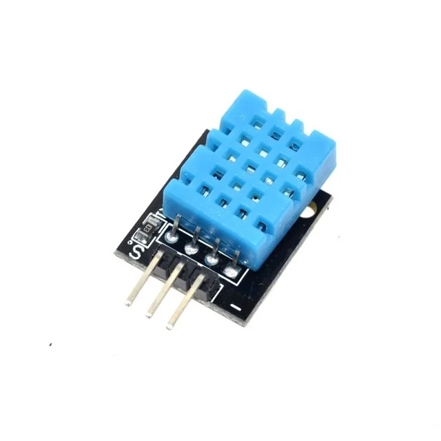
DHT11 Digital Relative Humidity and Temperature Sensor Module
Pair with your DIY anemometer to build a complete weather station. The DHT11 provides temperature data needed for wind chill calculations and humidity for moisture index readings.
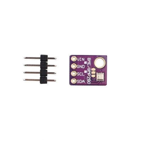
GY-BME280-5V Temperature and Humidity Sensor
The BME280 adds barometric pressure to your weather station — combine wind speed, temperature, humidity, and pressure for a fully professional amateur meteorology setup.
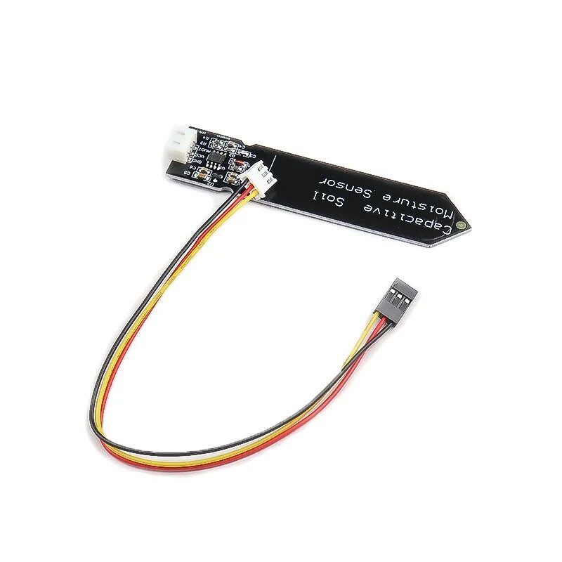
Capacitive Soil Moisture Sensor
Extend your weather station into an agricultural monitoring system. Combine wind speed data with soil moisture to automate irrigation — wind increases soil evaporation and affects when to water crops.
Frequently Asked Questions
Q1: What is the minimum wind speed a DIY cup anemometer can detect?
The minimum detectable wind speed (start-up speed) of a cup anemometer depends on the bearing friction and cup weight. A well-made DIY anemometer with a quality bearing typically starts at 1–2 km/h. Below this, the cups may not spin consistently. Commercial anemometers have start-up speeds as low as 0.5 km/h.
Q2: Can I use a reed switch instead of a Hall effect sensor?
Yes. A reed switch (with a magnet in the axle) is simpler to wire and doesn’t require a power supply. However, reed switches can bounce (multiple pulses per magnet pass) and may wear out after 1–2 million cycles (about 100 hours at 10 RPS). For long-term outdoor deployment, a Hall effect sensor is more reliable.
Q3: How do I convert from km/h to m/s or knots?
1 km/h = 0.2778 m/s = 0.5400 knots. In code: float ms = windSpeed / 3.6; and float knots = windSpeed / 1.852;. Use the Beaufort scale to classify wind force (0=calm, 12=hurricane) for weather station displays.
Q4: How accurate is a DIY anemometer compared to professional ones?
A well-calibrated DIY cup anemometer achieves ±5–10% accuracy, compared to ±1–2% for professional instruments (±3% for most commercial weather stations). For home weather monitoring and educational projects, ±10% is perfectly adequate. Agricultural IoT and drone wind checks benefit from the tighter ±5% achievable with car-speed calibration.
Q5: Can I add wireless data logging to this project?
Yes. Replace the Arduino Nano with an ESP8266 or ESP32 to add Wi-Fi. Log data to a free service like ThingSpeak, Blynk, or your own MQTT broker. Set up a Node-RED dashboard to plot wind speed and direction over time. The ESP8266 can also send wind speed alerts via Telegram bot if gusts exceed a threshold.
Q6: What types of projects is this wind station useful for in India?
In India, DIY wind stations are useful for: monitoring rooftop wind conditions before installing small wind turbines, agricultural wind break planning, construction site safety (crane operation wind limits), amateur meteorology for IMD data validation, drone pilot site surveys, and school and college science fair projects.
Find all the sensors, microcontrollers, and modules you need to build a complete weather monitoring station at Zbotic’s Sensors & Measurement store. Fast delivery to all Indian cities with expert support for your DIY projects.


Add comment