
Table of Contents
- Introduction to HC-SR501 PIR Sensor
- How PIR Sensors Detect Motion
- Hardware Overview and Pinout
- Sensitivity Adjustment (Sx Potentiometer)
- Time Delay Adjustment (Tx Potentiometer)
- H vs L Trigger Modes Explained
- Wiring HC-SR501 to Arduino
- Arduino Code for Motion Detection
- Advanced Projects and Use Cases
- Troubleshooting Common Issues
- Frequently Asked Questions
Introduction to HC-SR501 PIR Sensor
The HC-SR501 PIR (Passive Infrared) sensor is one of the most widely used motion detection modules in the Arduino and DIY electronics community. Whether you are building a smart home security system, an automatic lighting controller, or a visitor counter, the HC-SR501 offers an affordable and reliable solution that works right out of the box — provided you know how to tune it properly.
What makes this sensor truly versatile is its two onboard potentiometers that let you independently control detection sensitivity and output time delay. Most beginners plug in the module and accept the factory defaults, but understanding how to tune these parameters transforms the HC-SR501 from a basic motion detector into a precisely calibrated sensing device suited for professional-grade applications.
In this comprehensive guide, we will cover everything from the physics of infrared detection to hands-on Arduino code examples. By the end, you will be able to dial in exactly the detection range and trigger duration you need for any project.
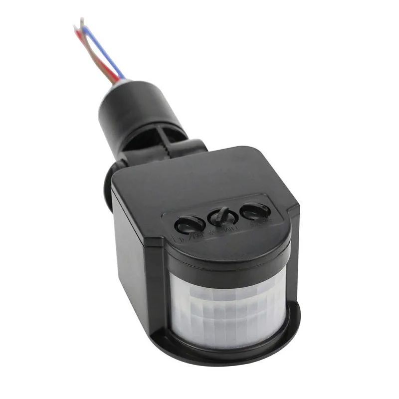
AC 220V Security PIR Human Body Motion Sensor Detector Coil LED Light Switch
A high-voltage PIR module for direct mains-powered lighting control — ideal for stairways and corridors where you need no microcontroller at all.
How PIR Sensors Detect Motion
The term “passive” in Passive Infrared means the sensor does not emit any energy of its own. Instead, it passively detects infrared radiation — essentially heat — emitted by warm objects such as the human body, animals, and even hot surfaces.
Inside the HC-SR501 sits a pyroelectric sensing element divided into two halves. Each half generates a small voltage when exposed to infrared radiation. When the scene is static, both halves receive equal IR levels and the differential output is zero. The moment a warm object moves across the sensor’s field of view, one half receives more IR than the other, producing a differential signal that the onboard BISS0001 chip amplifies and converts into a digital HIGH output on the signal pin.
The white plastic Fresnel lens on top is not decorative — it segments the sensor’s field of view into many small zones, amplifying the differential effect and extending detection range. The lens pattern determines the detection cone (typically 110° horizontal, 70° vertical for the HC-SR501).
Key Specifications at a Glance
- Supply Voltage: 4.5V – 20V DC
- Output Voltage: 3.3V HIGH, 0V LOW
- Detection Range: Up to 7 metres (adjustable)
- Detection Angle: Less than 120°
- Time Delay Range: ~0.3 seconds – ~5 minutes (adjustable)
- Operating Temperature: -15°C to +70°C
- Quiescent Current: Less than 50 µA
Hardware Overview and Pinout
Flip the HC-SR501 board over and you will find a straightforward three-pin connector and two orange potentiometers. Here is what each element does:
Pin Description
| Pin | Label | Description |
|---|---|---|
| 1 | VCC | Power supply 5V–12V DC |
| 2 | OUT | Digital output (HIGH = motion detected) |
| 3 | GND | Ground reference |
Onboard Components
- Sx Potentiometer (Sensitivity): Located closer to the edge. Rotating clockwise increases detection distance; counter-clockwise reduces it.
- Tx Potentiometer (Time Delay): Located toward the centre. Rotating clockwise increases the output HIGH duration; counter-clockwise decreases it.
- Jumper (L/H Mode): A 3-pin jumper near the potentiometers that selects repeatable (H) or non-repeatable (L) trigger mode.

B2X2 4 Elements Infrared Motion Analog PIR sensor for Lighting
A quad-element PIR sensor with analog output — great when you need directionality or want to feed raw IR data to an ADC for custom processing.
Sensitivity Adjustment (Sx Potentiometer)
The sensitivity potentiometer directly controls the gain of the BISS0001 comparator stage. In practical terms, it determines how far away the sensor can reliably detect a human walking across its field of view.
Adjusting Sensitivity Step by Step
- Power up the module and wait for the 30–60 second initialisation period to complete. During this time, the output pin may fire repeatedly — this is normal.
- Set the Tx potentiometer to the minimum (full counter-clockwise) so output pulses are short and easy to observe.
- Walk in front of the sensor at the maximum distance you want to detect. If the LED on your Arduino does not light, slowly rotate Sx clockwise until detection is reliable.
- Then walk very close to the sensor. If false triggers occur from furniture or air currents, rotate Sx counter-clockwise until they stop.
- The sweet spot is the highest sensitivity setting that avoids consistent false positives in your deployment environment.
Practical Sensitivity Ranges
At full clockwise, the HC-SR501 can detect a walking human at up to 7 metres in a clear room. At minimum sensitivity, the range drops to roughly 3 metres. For a corridor sensor where you only want to detect someone passing within 2 metres, running Sx at about one-third will prevent the sensor from triggering on activity in adjacent rooms.
Pro tip: Temperature affects PIR sensitivity. In a hot Indian summer where ambient temperature approaches body temperature, sensitivity naturally decreases. Compensate by rotating Sx slightly clockwise during warmer months.
Time Delay Adjustment (Tx Potentiometer)
The time delay potentiometer sets how long the output pin stays HIGH after motion is last detected. This is the parameter that most beginners overlook, yet it critically affects how your firmware responds to motion events.
Time Delay Range
The HC-SR501’s time delay spans from approximately 0.3 seconds (full counter-clockwise) to around 5 minutes (full clockwise), though exact values vary slightly between manufacturers. The relationship is not linear — the last 20% of clockwise rotation covers the longest delays, so fine adjustment at maximum delay is difficult.
Choosing the Right Delay for Your Application
| Application | Recommended Tx Setting | Reason |
|---|---|---|
| Visitor counter (short pulse per person) | Minimum (~0.3s) | Count each crossing separately |
| Security alarm trigger | 2–5 seconds | Enough time for alarm to activate before person leaves frame |
| Automatic corridor light | 30–60 seconds | Keeps light on while someone is still present |
| Sleep tracking / night mode | 2–3 minutes | Avoids repeated wake-ups from minor movements |
H vs L Trigger Modes Explained
The three-pin jumper selects between two fundamentally different behaviours:
L Mode (Non-Repeatable Trigger)
When set to L, the sensor fires a single HIGH pulse each time motion is detected. Once the Tx delay expires, the output goes LOW even if motion is still occurring. The output will not go HIGH again until there has been a period of no motion, then new motion is detected. This mode is useful when you want to count distinct motion events.
H Mode (Repeatable Trigger)
In H mode, every new motion detection resets the Tx timer. As long as someone remains in the detection zone and keeps moving, the output stays HIGH indefinitely. The output only goes LOW once the person has been completely still for the full Tx duration. This is the correct mode for automatic lighting — the light stays on the entire time someone is in the room.
Default from factory: Most HC-SR501 modules ship with the jumper in H position.
Wiring HC-SR501 to Arduino
Connecting the HC-SR501 to an Arduino Uno is a three-wire job:
HC-SR501 VCC  →  Arduino 5V
HC-SR501 GND  →  Arduino GND
HC-SR501 OUT  →  Arduino Digital Pin 2
Note: The HC-SR501 output is 3.3V HIGH, which is within the logic-high threshold of Arduino digital pins. No level shifter is needed. However, powering the sensor from 5V (rather than the 3.3V rail) is recommended because it ensures the BISS0001 chip operates at its rated voltage for consistent performance.
If you are using a 3.3V board such as the ESP8266 or ESP32, power the HC-SR501 from 5V if available (many development boards have a 5V pin) but connect the signal wire directly to your 3.3V GPIO — the 3.3V output level from the sensor is perfectly safe for 3.3V inputs.
Arduino Code for Motion Detection
Below are three progressively more advanced Arduino sketches to get you started.
Sketch 1: Basic Motion Alert
const int PIR_PIN = 2;
const int LED_PIN = 13;

void setup() {
  pinMode(PIR_PIN, INPUT);
  pinMode(LED_PIN, OUTPUT);
  Serial.begin(9600);
  Serial.println("Waiting for PIR to initialise...");
  delay(30000); // 30-second warm-up
  Serial.println("PIR ready.");
}

void loop() {
  int motionState = digitalRead(PIR_PIN);
  if (motionState == HIGH) {
    digitalWrite(LED_PIN, HIGH);
    Serial.println("Motion detected!");
  } else {
    digitalWrite(LED_PIN, LOW);
  }
  delay(100);
}
Sketch 2: Motion Event Counter with Debounce
const int PIR_PIN = 2;
int motionCount = 0;
bool lastState = LOW;
unsigned long lastTriggerTime = 0;
const unsigned long DEBOUNCE_MS = 1000; // 1 second gap between counts

void setup() {
  pinMode(PIR_PIN, INPUT);
  Serial.begin(9600);
  delay(30000);
  Serial.println("Counter ready.");
}

void loop() {
  bool currentState = digitalRead(PIR_PIN);
  unsigned long now = millis();

  // Rising edge detection with debounce
  if (currentState == HIGH && lastState == LOW) {
    if (now - lastTriggerTime > DEBOUNCE_MS) {
      motionCount++;
      lastTriggerTime = now;
      Serial.print("Motion count: ");
      Serial.println(motionCount);
    }
  }
  lastState = currentState;
  delay(50);
}
Sketch 3: Interrupt-Driven Motion Logger
const int PIR_PIN = 2; // Must be pin 2 or 3 for Uno interrupts
volatile bool motionFlag = false;

void motionISR() {
  motionFlag = true;
}

void setup() {
  pinMode(PIR_PIN, INPUT);
  Serial.begin(9600);
  attachInterrupt(digitalPinToInterrupt(PIR_PIN), motionISR, RISING);
  delay(30000);
  Serial.println("Interrupt-based PIR ready.");
}

void loop() {
  if (motionFlag) {
    motionFlag = false;
    Serial.print("[Motion @ ms: ");
    Serial.print(millis());
    Serial.println("]");
    // Place your event handler here
  }
  // Main loop is free to do other work
}
The interrupt-driven approach is the most efficient as it frees the main loop for other tasks while reliably capturing every motion event regardless of loop timing.
Advanced Projects and Use Cases
1. Smart Corridor Lighting with Relay
Connect a 5V relay module between Arduino pin 3 and a mains LED bulb. Set HC-SR501 to H mode with Tx at 60 seconds. When motion is detected, the relay closes and the light turns on. It automatically shuts off 60 seconds after the last movement — perfect for hostel corridors or staircases.
2. Intruder Alert with SMS via GSM Module
Combine the HC-SR501 with a SIM800L GSM module. When motion is detected at night (add a light-dependent resistor to gate nighttime-only alerts), send an SMS to a predefined number. Add a buzzer for a local alarm. The entire system can run on a 12V 7Ah SLA battery for several days without mains power.
3. Baby Monitor Movement Alarm
Mount an HC-SR501 pointing at a crib. Set sensitivity to minimum (short range) and Tx to 5 seconds in L mode. If the baby stops moving for more than 30 seconds (use a software timer on the Arduino), trigger an alarm. This is a simple check for sudden stillness rather than a medical device, but gives parents peace of mind.
4. Automatic PC Screen Saver Trigger
Connect HC-SR501 OUT to a USB HID device (like a Digispark). When no motion is detected for 10 minutes, simulate pressing a key to let the OS screen saver kick in. When motion resumes, wake the screen. This works without installing any software on the host PC.

AC110-240V PIR Infrared Motion Sensor Switch with Terminal Line
A wiring-terminal PIR switch for direct integration into Indian 230V home wiring — no microcontroller needed for basic on/off switching.
Troubleshooting Common Issues
Sensor Fires Continuously with No Movement
This is almost always an initialisation issue. The HC-SR501 requires 30–60 seconds after power-on to establish a thermal baseline. All outputs during this window are invalid. Ensure your code does not act on motion events during this period. Also check that nothing is radiating heat near the sensor (power supplies, CPUs, warm walls in direct sunlight).
Sensor Does Not Detect at Close Range
The HC-SR501 has a minimum detection distance of roughly 0.5 metres due to the Fresnel lens geometry. Objects closer than 50 cm may not produce enough differential IR change across the two sensor halves. Consider removing the Fresnel lens for very close-range applications, though this dramatically narrows the field of view.
Erratic Behaviour on Battery Power
PIR sensors are sensitive to supply voltage fluctuations. Add a 100 µF electrolytic capacitor between VCC and GND close to the sensor module. Also ensure your battery can supply at least 4.5V under load — a 3 × AA pack can drop below this when nearly depleted.
Output Stays HIGH for Too Long
Your Tx potentiometer is set too high. Rotate it counter-clockwise. If it is already at minimum and still too long, check whether the sensor is in H mode (with the jumper) — in H mode, continuous background movement (like a ceiling fan) can keep the output permanently HIGH. Switch to L mode or shield the sensor from the offending heat source.
Detection Range Inconsistent Between Sensors
The HC-SR501 is a budget sensor and component tolerances between units vary. If you are building a product that requires consistent detection ranges, consider calibrating each unit individually or upgrading to a sensor like the RCWL-0516 microwave module which has more consistent characteristics.
Frequently Asked Questions
What is the initialisation delay of the HC-SR501?
The HC-SR501 requires approximately 30 to 60 seconds after power-up to stabilise its internal reference. During this window, the output pin may fire multiple times. Always wait for this initialisation period to complete before treating output signals as valid motion events. In firmware, add a delay(30000) or equivalent timer at startup.
Can I use HC-SR501 with ESP8266 or ESP32?
Yes. The sensor output is 3.3V HIGH, which is directly compatible with ESP8266 and ESP32 GPIO inputs. Power the sensor’s VCC from the 5V pin on your development board (if available) for reliable operation, and connect the signal pin to any standard digital GPIO.
What is the difference between H and L trigger modes?
H (High) mode keeps the output HIGH as long as motion continues to be detected, resetting the Tx timer on every new motion event. L (Low) mode fires a single fixed-duration pulse per motion event and does not extend on additional movement. Use H mode for lights and alarms; use L mode for counting distinct events.
How do I reduce false triggers?
First, rotate the Sx potentiometer counter-clockwise to reduce sensitivity. Second, shield the sensor from heat sources like bulbs, radiators, and sunlit windows. Third, add a software debounce or minimum event gap in your Arduino code. Fourth, consider placing the sensor away from air conditioning vents, as temperature gradients from moving air can occasionally trigger PIR sensors.
Can HC-SR501 detect animals like dogs or cats?
Yes. Any warm-bodied animal that moves through the field of view will trigger the HC-SR501. However, smaller animals may not produce a strong enough differential signal at longer ranges, especially if sensitivity is set low. A cat at 3 metres should be detectable at maximum sensitivity; a mouse at 2 metres typically will not trigger the sensor reliably.
What is the operating voltage for the HC-SR501?
The HC-SR501 accepts a supply voltage between 4.5V and 20V DC. For Arduino projects, 5V is the standard choice. The onboard regulator handles the rest, ensuring the BISS0001 chip always sees an appropriate voltage regardless of the supply level within this range.
Ready to start your motion detection project? Browse Zbotic’s full range of PIR sensors, relay modules, and Arduino-compatible boards. All products ship across India with fast delivery. Shop Sensors & Modules at Zbotic →


Add comment