
Soil NPK sensors measure the three primary plant nutrients — nitrogen (N), phosphorus (P), and potassium (K) — directly in the soil. Combined with RS485 communication and Modbus RTU protocol, these sensors can be connected to Arduino microcontrollers for precision agriculture applications, smart irrigation systems, and automated fertiliser dosing.
This comprehensive tutorial covers everything you need to connect a soil NPK sensor (RS485) to Arduino using Modbus RTU — wiring, library installation, register maps, Arduino code, and data interpretation for real-world agriculture use.
Soil NPK Sensor Overview
Soil NPK sensors use electrical conductivity and dielectric measurements to estimate nitrogen, phosphorus, and potassium concentrations in the soil. While they are not as precise as laboratory wet chemistry analysis, they provide fast, in-situ readings that are valuable for tracking relative changes and guiding fertiliser decisions.
The most common form factor available in India in 2026 is a stainless-steel probe with a 7-pin RS485 connector. These sensors typically measure:
- Nitrogen (N): 0–1,999 mg/kg
- Phosphorus (P): 0–1,999 mg/kg
- Potassium (K): 0–1,999 mg/kg
Many models also measure soil moisture, electrical conductivity (EC), pH, and temperature as secondary outputs in the same register map.
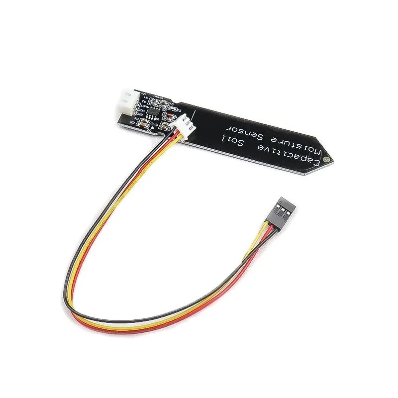
Capacitive Soil Moisture Sensor
Pair a capacitive moisture sensor with your NPK probe for a complete soil health station covering moisture, nutrients, and salinity.
Understanding RS485 and Modbus RTU
What is RS485?
RS485 is a differential serial communication standard designed for industrial environments. It uses two wires (A+ and B−) to transmit data. The differential signalling makes it highly resistant to electrical noise — critical in field deployments where cables run near motors, pumps, and solenoids.
Key advantages of RS485 over UART or I2C for outdoor sensor applications:
- Cable runs up to 1,200 metres
- Up to 32 devices on one bus (with standard drivers)
- Excellent noise immunity in high-EMI environments
- Common in industrial and agricultural equipment
What is Modbus RTU?
Modbus is a serial communication protocol originally developed by Modicon in 1979. It is the dominant protocol for industrial sensors, PLCs, and field instruments worldwide. Modbus RTU is the binary-encoded version that runs on RS485 physical layer.
In Modbus RTU, a master device (your Arduino) sends a request frame to a slave device (the NPK sensor) specifying a function code (typically 0x03 — Read Holding Registers) and the register addresses to read. The sensor responds with the data values.
Components Required
- Soil NPK sensor with RS485 output (7-pin connector)
- Arduino Uno, Nano, or Mega
- MAX485 or TTL-to-RS485 breakout module
- 12 V DC power supply (most NPK sensors require 9–24 V)
- Jumper wires, breadboard, and screw terminal block
- 120 Ω termination resistor (if cable length exceeds 1 metre)
Wiring: NPK Sensor to Arduino via RS485 Module
The NPK sensor’s RS485 wires are connected to the MAX485 module, which in turn connects to Arduino via UART (Software Serial or Hardware Serial).
NPK Sensor Connector Pinout (typical 7-pin model)
| Wire Colour | Signal |
|---|---|
| Brown | Power+ (12–24 V DC) |
| Black | Power GND |
| Yellow | RS485 A+ |
| Blue | RS485 B− |
Note: Wire colours vary by manufacturer. Always verify against your sensor’s datasheet before wiring.
MAX485 Module to Arduino Connections
| MAX485 Pin | Arduino Pin |
|---|---|
| VCC | 5V |
| GND | GND |
| DI (data in) | D11 (TX) |
| RO (receive out) | D10 (RX) |
| DE + RE (tied together) | D9 (Direction control) |
| A | NPK Sensor A+ |
| B | NPK Sensor B− |
Power note: The NPK sensor typically requires 12 V DC, NOT 5 V. Power it from a dedicated 12 V supply. Share only the GND between the 12 V supply and the Arduino/MAX485 circuit (common ground).
Termination: If your RS485 cable is longer than 1 metre (which it usually is in field deployments), add a 120 Ω resistor between the A and B lines at the far end of the bus.
Modbus Register Map
The register map varies slightly by sensor manufacturer but the most common layout is:
| Register (hex) | Parameter | Unit | Scale |
|---|---|---|---|
| 0x0000 | Nitrogen (N) | mg/kg | × 1 |
| 0x0001 | Phosphorus (P) | mg/kg | × 1 |
| 0x0002 | Potassium (K) | mg/kg | × 1 |
| 0x0003 | Soil Moisture | % | × 0.1 |
| 0x0004 | Temperature | °C | × 0.1 |
| 0x0005 | Electrical Conductivity (EC) | µS/cm | × 1 |
| 0x0006 | pH | — | × 0.1 |
Default Modbus address is usually 0x01 (device ID 1). Default baud rate is 9600 or 4800 — check your sensor datasheet.
Arduino Modbus Library Setup
Install the ModbusMaster library by Doc Walker via the Arduino Library Manager (search: ModbusMaster). This library handles all Modbus RTU framing, CRC calculation, and register addressing automatically.
Alternatively, install via Arduino CLI:
arduino-cli lib install "ModbusMaster"Full Arduino Code: Read NPK Values
#include <SoftwareSerial.h>
#include <ModbusMaster.h>

// RS485 direction control pin
#define DE_RE_PIN 9

// SoftwareSerial on pins 10 (RX), 11 (TX)
SoftwareSerial rs485Serial(10, 11);

// ModbusMaster node, address 0x01
ModbusMaster node;

void preTransmission() {
  digitalWrite(DE_RE_PIN, HIGH); // Enable transmit
}

void postTransmission() {
  digitalWrite(DE_RE_PIN, LOW);  // Enable receive
}

void setup() {
  Serial.begin(9600);
  rs485Serial.begin(9600);

  pinMode(DE_RE_PIN, OUTPUT);
  digitalWrite(DE_RE_PIN, LOW); // Start in receive mode

  node.begin(1, rs485Serial); // Slave address 1
  node.preTransmission(preTransmission);
  node.postTransmission(postTransmission);

  Serial.println("Soil NPK Sensor - Modbus RTU Reader");
  Serial.println("------------------------------------");
}

void loop() {
  uint8_t result;
  uint16_t data[7]; // 7 registers: N, P, K, Moisture, Temp, EC, pH

  // Read 7 holding registers starting at address 0x0000
  result = node.readHoldingRegisters(0x0000, 7);

  if (result == node.ku8MBSuccess) {
    for (int i = 0; i < 7; i++) {
      data[i] = node.getResponseBuffer(i);
    }

    Serial.print("Nitrogen (N):   "); Serial.print(data[0]); Serial.println(" mg/kg");
    Serial.print("Phosphorus (P): "); Serial.print(data[1]); Serial.println(" mg/kg");
    Serial.print("Potassium (K):  "); Serial.print(data[2]); Serial.println(" mg/kg");
    Serial.print("Moisture:       "); Serial.print(data[3] * 0.1, 1); Serial.println(" %");
    Serial.print("Temperature:    "); Serial.print(data[4] * 0.1, 1); Serial.println(" C");
    Serial.print("EC:             "); Serial.print(data[5]); Serial.println(" uS/cm");
    Serial.print("pH:             "); Serial.println(data[6] * 0.1, 1);
    Serial.println();
  } else {
    Serial.print("Modbus error code: 0x");
    Serial.println(result, HEX);
  }

  delay(2000); // Wait 2 seconds between readings
}
Open the Serial Monitor at 9600 baud. You should see NPK and other values printed every 2 seconds. If you see Modbus error codes, refer to the troubleshooting section.
Common Modbus Error Codes
| Error Code (hex) | Meaning |
|---|---|
| 0xE0 | Invalid slave ID — check sensor address |
| 0xE1 | Invalid function — check register map |
| 0xE2 | Response timed out — wiring or baud rate problem |
| 0xE3 | Invalid CRC — noise on the RS485 bus |
Interpreting NPK Readings
Raw NPK values in mg/kg need context to be actionable. The following table provides general guidance for Indian agricultural soils:
| Nutrient | Low | Medium | High |
|---|---|---|---|
| Nitrogen (N) | < 280 kg/ha | 280–560 kg/ha | > 560 kg/ha |
| Phosphorus (P) | < 11 kg/ha | 11–22 kg/ha | > 22 kg/ha |
| Potassium (K) | < 110 kg/ha | 110–280 kg/ha | > 280 kg/ha |
Important caveat: The NPK sensor measures available nutrient proxies in mg/kg soil weight, not actual extractable nutrient levels. Treat readings as relative indicators for trend monitoring rather than absolute values for fertiliser prescription. Calibrate against soil lab tests for your specific soil type.
Connecting Multiple Sensors on One RS485 Bus
One of the main advantages of RS485/Modbus is the ability to daisy-chain multiple sensors on a single pair of wires. Each sensor must have a unique Modbus address (1–247).
To change the address of your NPK sensor, write to the address configuration register (typically register 0x07 or 0x0100 depending on manufacturer). Consult your sensor’s datasheet for the exact procedure — it usually involves sending a specific write function code (0x06) command.
// Example: Write new slave address 2 to register 0x07
result = node.writeSingleRegister(0x07, 0x0002);
if (result == node.ku8MBSuccess) {
  Serial.println("Address changed to 2. Power cycle the sensor.");
}
With multiple sensors, iterate through addresses in your loop:
// Query sensor at address 1, then address 2
for (uint8_t addr = 1; addr <= 2; addr++) {
  node.begin(addr, rs485Serial);
  result = node.readHoldingRegisters(0x0000, 3);
  // ... process result
}
Data Logging and IoT Integration
For precision agriculture deployments, NPK data becomes valuable when logged over time and visualised.
SD Card Logging (Arduino Mega)
Use the SD library to log timestamped NPK readings to a CSV file on an SD card. Combine with a DS3231 RTC module for accurate timestamps.
ESP32 + MQTT for Remote Monitoring
Replace Arduino Uno with an ESP32 or connect an ESP-01 via UART. Publish NPK values to an MQTT broker (Mosquitto on a Raspberry Pi, or cloud services like Adafruit IO, HiveMQ). Build a Node-RED dashboard for real-time visualization.
LoRaWAN for Wide-Area Farms
For sensor nodes spread across large farms, pair the Arduino + NPK sensor with a LoRa module (SX1276 or RAK wireless node). Transmit readings to a central gateway at the farm office every 15–30 minutes. This architecture covers distances of 2–10 km with minimal power — suitable for battery-powered field nodes.

DIY Automatic Irrigation Module — Soil Moisture Detection
Combine NPK sensor data with this automatic irrigation module to build a closed-loop nutrient and moisture management system.

BMP280 Barometric Pressure and Altitude Sensor
Add atmospheric pressure and temperature monitoring to complement your soil NPK station for a complete microclimate sensor array.
Frequently Asked Questions
Q: My NPK sensor returns 0xE2 (timeout) every time. What is wrong?
A: Most commonly this is a baud rate mismatch. Try 4800, 9600, and 19200 in your SoftwareSerial.begin() call. Also verify the DE/RE pin is correctly switching between transmit and receive mode — many failures stem from the direction control pin staying HIGH (transmit) instead of switching back to receive after sending the query.
Q: Can I use Hardware Serial (pins 0/1) instead of SoftwareSerial?
A: Yes and it is actually more reliable. On Arduino Mega, use Serial1, Serial2, or Serial3 (pins 18-19, 16-17, 14-15). On Arduino Uno, Hardware Serial is shared with the USB-to-serial chip — you cannot use it for RS485 and Serial Monitor simultaneously. Use SoftwareSerial on Uno or switch to a Mega/Leonardo for hardware serial.
Q: Does the NPK sensor need to be buried to work?
A: For accurate NPK readings, yes — the electrodes need to be in contact with moist soil. Insert the probe to the measurement depth for your crop (typically 10–20 cm for most vegetable crops). Dry soil gives low or zero readings.
Q: How often should I take NPK readings?
A: For trend monitoring, daily readings at the same time and soil moisture condition are most useful. Do not compare readings taken in dry soil versus wet soil — moisture affects the electrical measurement and creates apparent nutrient changes.
Q: What is the difference between soil NPK sensors and laboratory soil tests?
A: Laboratory tests (Olsen phosphorus, exchangeable potassium, total nitrogen) use chemical extraction to measure actual plant-available nutrient concentrations. NPK sensors use electrical proxies that correlate with nutrients but are influenced by soil texture, organic matter, and moisture. Lab tests are more accurate; NPK sensors are faster and enable continuous monitoring.
Conclusion
Connecting a soil NPK sensor to Arduino via RS485 Modbus RTU gives hobbyists, students, and precision agriculture developers a powerful tool for real-time soil health monitoring. The combination of robust RS485 differential signalling, the simple Modbus protocol, and the accessible ModbusMaster Arduino library makes integration straightforward once you understand the wiring and register map.
Extend this project with data logging, wireless transmission, or automated fertigation control — the Zbotic store has the sensors, modules, and components you need to build your complete precision agriculture system.
Build Your Precision Agriculture Sensor Station
Shop soil sensors, relay modules, and microcontroller boards at Zbotic — fast delivery across India.


Add comment