
You wire up your motor driver, upload your code, and the robot moves perfectly — for about two seconds. Then the Arduino resets, the motors twitch erratically, or one motor spins slower than the other. The culprit in the vast majority of these cases is voltage drop on the motor driver supply line. It is one of the most common and most misunderstood problems in hobbyist robotics, and fixing it completely transforms how reliable your project becomes.
This guide covers exactly what causes voltage drop, how to measure it, what damage or malfunction it causes, and every practical prevention method — from simple capacitor tricks to proper power supply design.
What Is Voltage Drop in Motor Circuits?
Voltage drop is the reduction in voltage measured between two points in a circuit due to the resistance of conductors, connectors, switches, and semiconductor junctions carrying current. Ohm’s Law states V = I × R. In motor circuits, current (I) can be very large — a single DC motor can draw 1–5A at stall. Even a small resistance (R) of 0.1Ω in the supply path creates a 0.5V drop at 5A of current.
For a 12V motor driver supplying two motors, 0.5V drop may seem insignificant. But consider the chain: battery internal resistance → connector resistance → wire resistance → motor driver input trace resistance → H-bridge transistor saturation voltage → motor terminal. Each element adds drop. The cumulative loss can reach 2–3V, meaning your motor sees 9–10V instead of 12V — a 16–25% power reduction.
During motor startup (the worst case), current spikes to 5–10× the running current. Voltage drop spikes proportionally. This is when brownouts and resets occur.
Root Causes of Voltage Drop
1. Insufficient Wire Gauge
Thin wire (24 AWG or 26 AWG commonly found in dupont jumper cables) has high resistance per meter. At 2A, a 30cm pair of 26 AWG wires can drop 0.3–0.5V. For motor power, use 20 AWG or thicker. Silicone-insulated wire from RC/FPV suppliers is excellent — flexible, high-current-rated, and available in India.
2. Connector Resistance
Dupont connectors have contact resistance of 0.01–0.05Ω each — negligible for signal lines but significant for motor power. At 3A through two connectors in series, you can lose 0.3V. Use screw terminals or soldered connections for motor power. XT30/XT60 connectors rated for 30A+ are much better for motor power distribution.
3. Underpowered / High Internal Resistance Supply
A 9V alkaline battery has internal resistance of 0.5–2Ω depending on charge state. At 3A motor draw, that’s 1.5–6V dropped internally — completely inadequate. Even some 2A USB power banks have poor regulation under transient loads. Use lipo batteries (internal resistance 10–50mΩ) or dedicated bench power supplies for any serious motor project.
4. H-Bridge Saturation Voltage
Bipolar H-bridge ICs like the L298N have two power transistors in series in the current path. Each transistor has a saturation voltage (Vce_sat) of approximately 1.4–2V. With two transistors in series, the L298N wastes up to 4V as heat. On a 6V motor supply, you lose 4V — meaning the motor only sees 2V. This is the infamous L298N voltage drop problem.
5. Shared Ground Impedance
If motor ground and logic ground share a single thin wire back to the battery, motor current causes a voltage difference on that ground wire. This lifts the motor driver’s ground reference above the Arduino’s ground — causing incorrect voltage readings on ADC pins, false interrupts, and communication errors.
Symptoms: How to Recognise Voltage Drop Problems
- Arduino resets when motor starts — most classic symptom. Motor inrush pulls supply voltage below 4.5V, triggering the Arduino’s brown-out detector.
- Motors slower than expected — measured battery voltage is fine but motors are weak and inefficient.
- One motor faster than the other — slight differences in wiring length/quality cause different drops to each motor.
- Serial monitor garbled during motor operation — ground noise from motor current corrupts UART signal levels.
- Ultrasonic/IR sensors give wrong readings when motors run — power rail noise couples into sensor supply.
- Motor driver gets very hot quickly — L298N at 4V Vce drop × 2A = 8W of heat. Normal for L298N, but a symptom of wasted power.
- Battery drains faster than expected — efficiency losses converted to heat reduce runtime.
How to Measure Voltage Drop with a Multimeter
This is the most important diagnostic step. Do not estimate — measure.
- Set your multimeter to DC Volts.
- Probe across the supply terminals: measure at the battery terminals (or PSU output) and simultaneously at the motor driver VIN pin.
- Run your motors at full load.
- The difference between the two readings is your supply-side voltage drop.
- Repeat: probe across the motor driver output terminals (motor A+/A−) vs the motor itself.
- For H-bridge internal drop: measure VIN at the driver, then measure voltage at motor terminals. The difference minus any wiring drop is the H-bridge’s contribution.
A healthy system should have less than 0.5V total drop from battery to motor under load. If you see 2V or more, you have a serious power delivery problem to fix.
Voltage Drop Inside the Motor Driver Itself
| Motor Driver IC | Technology | Typical Vdrop at 1A | Notes |
|---|---|---|---|
| L298N | Bipolar NPN | 3–4V | Very high, use ≥9V supply |
| L293D | Bipolar NPN | 2–3V | Drops above 600mA rated |
| TB6612FNG | MOSFET | 0.3–0.6V | Much better, 1.2A cont. |
| DRV8833 | MOSFET | 0.2–0.4V | Excellent for small motors |
| BTS7960 | MOSFET | 0.1–0.3V | 43A rated, low Rds_on |
| A4988 (stepper) | MOSFET | 0.2–0.5V | Current-regulated |
The key takeaway: if you are using an L298N with 5V or 6V motors, switch to a MOSFET driver. You are giving up 60–70% of your available motor voltage to transistor losses.
Prevention Method 1: Decoupling Capacitors
Capacitors cannot eliminate DC voltage drop from resistance, but they handle transient voltage dips caused by sudden current surges (motor startup, direction reversal). Add:
- 1000µF electrolytic capacitor across the motor driver’s VIN and GND pins. This bulk capacitor supplies transient current during motor startup without the full demand hitting the supply wiring.
- 100µF electrolytic + 100nF ceramic across each motor’s own terminals. Suppresses back-EMF spikes that would otherwise couple into the supply and logic rails.
- 100nF ceramic capacitor across Arduino VCC and GND pins. Filters high-frequency noise from PWM switching.
On breadboards, the capacitor wires must be short. Long jumper wires add inductance that defeats the capacitor’s purpose. Solder them directly to the motor driver module if possible.
Prevention Method 2: Proper Wiring Gauge & Length
For any motor drawing over 500mA, use:
- 20 AWG minimum for motor power wires up to 3A
- 18 AWG for 3–8A (BO motors, large N20s)
- 16 AWG or thicker for 8A+ applications
- Keep motor power wires as short as physically possible
- Twist the motor + and − wires together (reduces radiated EMI)
- Use soldered connections rather than press-fit dupont pins for power paths
Prevention Method 3: Correct Power Supply Selection
Match your supply to the peak (not average) current demand:
- Two BO motors at stall: ~1.5A each = 3A peak → use a 5A supply minimum
- Two NEMA17 steppers: ~1.2A each = 2.4A → use a 3A supply minimum
- Budget 50% headroom above calculated peak: a 4A rated supply has no margin; an 8A supply handles any surge without voltage sag
For battery-powered projects, LiPo cells are the correct choice for motors. A 2S (7.4V) 1000mAh 25C LiPo can deliver 25A burst current — far more than any small robot motor demands. Internal resistance under 50mΩ means voltage drop is below 0.15V even at 3A draw.
Prevention Method 4: Separate Logic and Motor Power
This is the single most effective reliability improvement for any motor project. Provide completely separate power rails for:
- Motor power (VM): Battery / high-current PSU → motor driver VM pin directly
- Logic power (VCC): Dedicated 5V linear or switching regulator → Arduino + sensor VCC
Connect the grounds together at a single point (star ground) near the battery. This prevents motor current flowing through the logic ground wire and corrupting signal references. Even a cheap LM7805 linear regulator providing isolated 5V to the Arduino is enough to eliminate most reset and noise problems.
Prevention Method 5: MOSFET vs Bipolar Driver Choice
When selecting a motor driver IC for a new design, choose MOSFET-based drivers unless there is a specific reason for bipolar. MOSFET H-bridges have on-state resistance (Rds_on) of 0.05–0.5Ω per switch, dropping only 0.1–0.5V at typical hobbyist currents. Bipolar drivers lose 1.5–2V per transistor in saturation — an order of magnitude worse.
Popular MOSFET motor driver modules available in India: TB6612FNG breakout, DRV8833, BTS7960 43A module. All are available for ₹60–300 and deliver 3–10× better efficiency than L298N for the same motor.
Ground Loops and Star Grounding
A ground loop forms when there are multiple return paths of different impedance for motor current. If motor current finds a path through the Arduino’s ground pin before returning to battery, it creates a voltage difference between the Arduino’s GND pin and the true battery negative. This can cause ADC offsets, digital I/O level shifts, and I2C/SPI communication errors.
Fix: implement star grounding. All ground wires (battery −, motor driver GND, Arduino GND, sensor GND) meet at a single copper pad or terminal block connected by a thick wire directly to battery negative. No ground wire carries return current of any other subsystem.
Battery Internal Resistance
| Battery Type | Typical Internal Resistance | Voltage Drop at 3A |
|---|---|---|
| 9V Alkaline (new) | 0.5–1Ω | 1.5–3V |
| AA NiMH (4-pack) | 0.1–0.3Ω | 0.3–0.9V |
| 2S LiPo 1000mAh | 0.02–0.05Ω | 0.06–0.15V |
| Li-Ion 18650 (1 cell) | 0.05–0.2Ω | 0.15–0.6V |
| USB Power Bank output | 0.3–1Ω (via boost converter) | 0.9–3V |
The data is clear: LiPo batteries are overwhelmingly superior for motor applications. A 9V alkaline battery is adequate only for the logic side, not for driving motors.
Recommended Products from Zbotic

A4988 Stepper Motor Driver Controller Board (RED)
MOSFET-based stepper driver with very low voltage drop compared to older bipolar drivers — ideal for CNC and 3D printer builds where precise positioning and efficiency both matter.

NEMA17 5.6 kg-cm Stepper Motor with Detachable Cable
High-quality NEMA17 motor with known coil resistance specs — pair with an A4988 or DRV8825 MOSFET driver for efficient operation with minimal voltage drop and thermal losses.
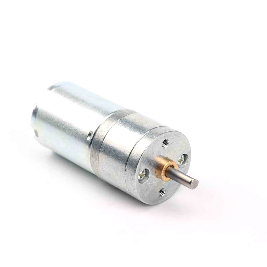
25GA-370 12V 1360RPM DC Reducer Gear Motor
A 12V DC geared motor with known current specs — run it from a 12V supply through a MOSFET H-bridge to get full speed with minimal voltage drop across the driver.
Frequently Asked Questions
Why does my Arduino reset every time the motor starts?
Motor startup current (inrush) is 5–10× the running current. This sudden demand drops the supply voltage below the Arduino’s brownout detection threshold (~4.5V for 5V Arduinos). Fix: add a 1000µF bulk capacitor across the motor driver VIN, use a dedicated regulated 5V supply for the Arduino separate from motor power, and/or use a lower-resistance power supply (LiPo instead of alkaline).
Is the L298N worth using anymore?
For 12V motors drawing under 1A, the L298N is acceptable — the 4V drop from a 12V supply is 33%, painful but liveable. For 5V or 6V motors it is effectively unusable. Modern MOSFET drivers (TB6612FNG, DRV8833) cost similar amounts and perform dramatically better. L298N has been around for 40 years and is still popular due to familiarity, not technical merit.
Can I add a bigger capacitor to completely fix voltage drop?
No. Capacitors handle transient (short-duration) voltage dips but cannot sustain DC current draw. A 1000µF capacitor stores about 1.5mJ at 12V — enough to supply a motor for a few milliseconds of startup, not seconds of running. For sustained voltage drop, you must reduce resistance in the supply path.
My motor driver gets very hot. Is that voltage drop?
Yes, partially. Power dissipated as heat in the driver = Vdrop × current. An L298N dropping 4V at 1A dissipates 4W as heat — hence the large heatsink required. Switching to a MOSFET driver dropping 0.5V at 1A dissipates only 0.5W — no heatsink needed and you recover that power for your motor.
How much voltage drop is acceptable?
As a rule of thumb: keep total voltage drop (wiring + connector + driver internal) under 5% of supply voltage. For a 12V system, under 0.6V is good. For a 5V system, under 0.25V. Any more than this meaningfully reduces motor performance and efficiency.
Shop efficient MOSFET-based motor drivers and quality motors at Zbotic’s Motors & Actuators collection. We stock A4988, stepper motors, DC gear motors, and accessories — all with fast delivery across India.


Add comment