
Building a robotic arm servo joystick arduino project is one of the most satisfying ways to learn about multi-axis motion control, servo mechanics, and real-time input processing. A joystick-controlled robotic arm mimics industrial pick-and-place machines, delta robots, and even surgical robots — all at a fraction of the cost. This tutorial takes you from zero to a fully functional 4-DOF robotic arm you can control with two analog joysticks, all with components sourced from within India.
Understanding Degrees of Freedom (DOF)
A robotic arm’s capability is defined by its degrees of freedom — the number of independent axes it can move along. More DOF means more flexibility in positioning the end effector (gripper) in 3D space:
- 1-DOF: A simple rotating arm that sweeps in one plane. Like a boom gate.
- 2-DOF: Shoulder + elbow. Reaches anywhere in a 2D plane at a fixed height.
- 3-DOF: Adds a rotating base (waist). Now reaches anywhere in 3D space within its reach envelope.
- 4-DOF: Adds wrist rotation or tilt. The gripper can approach an object from different angles.
- 5-DOF and 6-DOF: Full industrial arm capability. Any position and orientation in space.
For this tutorial, we’ll build a 4-DOF arm: waist rotation + shoulder + elbow + wrist pitch. A gripper adds the 5th axis. Two analog joysticks (4 axes total) map directly to these 4 joints, making this an intuitive and satisfying build.
Components You Need
| Component | Qty | Notes |
|---|---|---|
| Arduino Uno or Mega | 1 | Mega recommended for 6+ servos |
| MG996R Servo Motors (base, shoulder) | 2 | High torque for heavier joints |
| SG90 / MG90S Servo Motors (elbow, wrist) | 2–3 | Lighter joints need less torque |
| Acrylic Robotic Arm Kit or 3D printed frame | 1 | Pre-cut acrylic kits save hours |
| Analog Joystick Modules (KY-023) | 2 | Each gives X+Y axis + button |
| PCA9685 16-Channel PWM Driver | 1 | Offloads servo control from Arduino |
| 5V 5A Power Supply (for servos) | 1 | Never power servos from Arduino 5V! |
| Servo Brackets / Horn Mounts | 1 set | For arm joint construction |

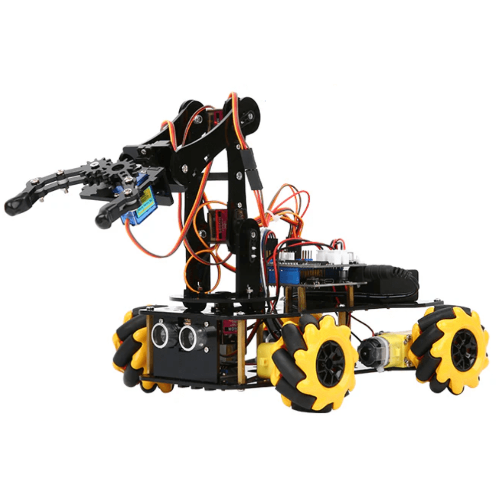
DIY Acrylic Robot Manipulator Mechanical Arm Kit
A pre-cut acrylic kit for building a multi-DOF robot arm. Includes all structural pieces — just add your servo motors and Arduino. Saves hours of fabrication time.
Choosing the Right Servo Motors
Servo selection is the most important mechanical decision in a robotic arm build. The wrong servo creates a floppy, unreliable arm. Here’s how to choose:
Torque calculation: The torque required at each joint depends on the weight of all components beyond that joint and their distance from the joint (lever arm). For example, if your elbow joint must support a 200g forearm + wrist + gripper assembly at a 15cm lever arm:
Torque = 200g × 15cm = 3000 g-cm = 3 kg-cm
Always add a 2× safety margin. So the elbow servo needs at least 6 kg-cm of torque.
SG90 (9g, 1.8 kg-cm): Only for the lightest joints — wrist tilt, gripper finger. Do not use for shoulder or base on anything except the lightest foam/cardboard arms.
MG90S (13.4g, 2.2 kg-cm, metal gear): Suitable for elbow and wrist on medium arms. Metal gears are essential — plastic gears strip under load.
MG996R (55g, 10–13 kg-cm): The workhorse for robotic arms. Use for base (waist rotation) and shoulder on arms up to 500g total weight. Metal gears, ball bearings, robust.
DS3225 (25 kg-cm, 270° range): For larger arms or when working with heavier payloads. Extended rotation range is useful for base joints.
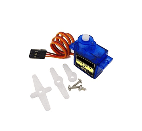
TowerPro SG90 180 Degree Rotation Servo Motor
The TowerPro SG90 is ideal for lightweight arm joints — wrist tilt and gripper control. 180° range, 9g weight, and direct Arduino compatibility via the Servo library.
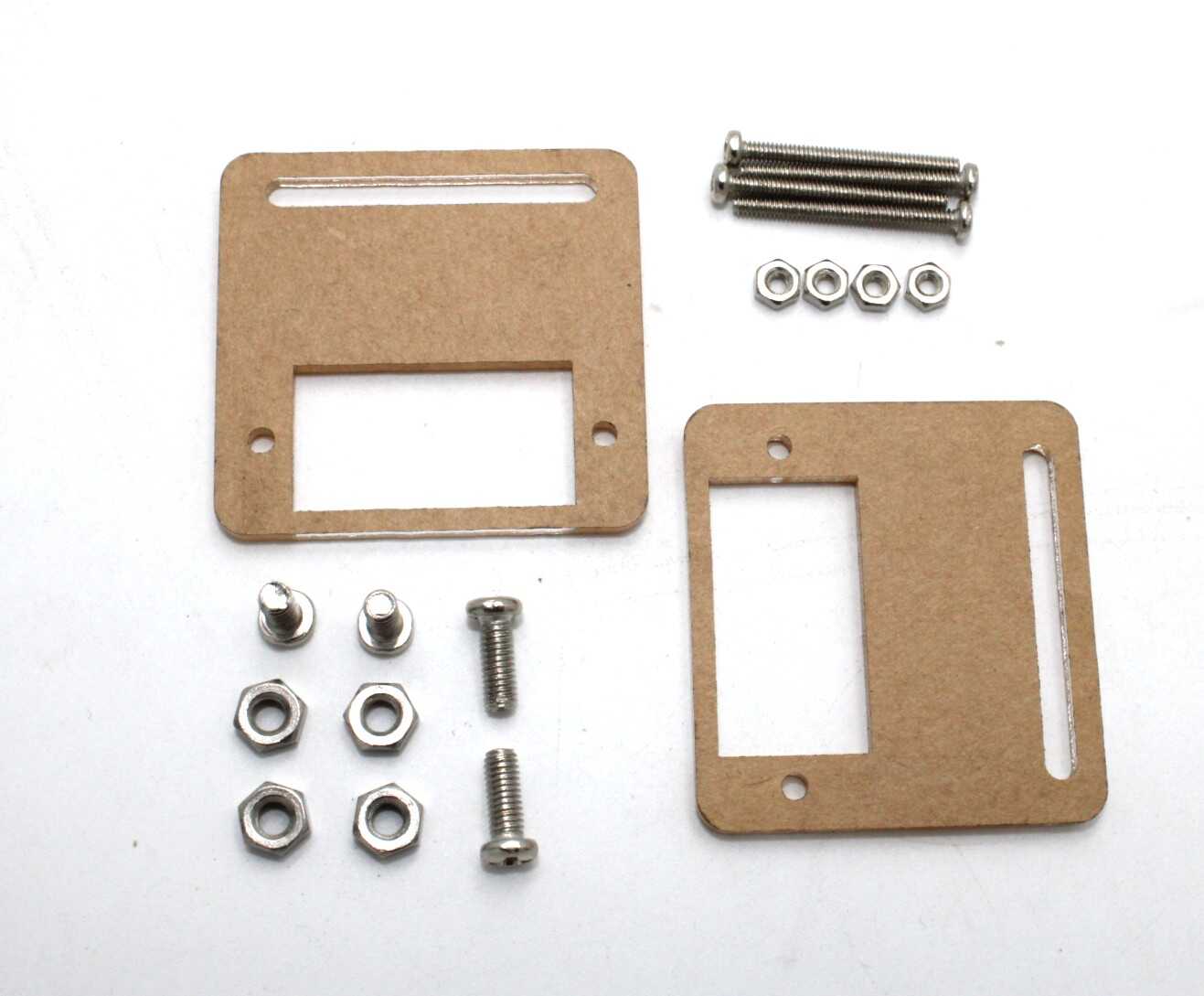
Servo Mount Holder Bracket for SG90/MG90 – Pack of 2
Metal servo mount brackets for building robot arm joints. Compatible with SG90 and MG90S servos. Rigid construction prevents flex that causes arm instability.
Assembling the Robotic Arm
Whether you’re using a pre-cut acrylic kit or 3D-printed parts, the assembly logic is the same. Start from the base and work upward:
- Base plate: Mount the first MG996R servo vertically at the center of the base plate. Its horn will rotate the entire arm. Use M3 bolts and lock nuts — vibration will loosen screws over time.
- Waist link: Attach the arm’s first link to the base servo horn. This link connects the base rotation servo to the shoulder servo.
- Shoulder joint: Mount the second MG996R horizontally on the waist link. Its horn connects to the upper arm link. Keep the servo axis aligned exactly with the joint center — misalignment causes binding.
- Upper arm + elbow: The upper arm link spans from shoulder to elbow. The elbow servo (MG90S or SG90) is at the far end, connecting to the forearm link.
- Forearm + wrist: The wrist servo provides pitch (up/down tilt of the end effector). For wrist roll (rotation), you need a 5th servo.
- Gripper: A simple servo-driven parallel gripper is the easiest to implement. One servo moves both fingers symmetrically via a linkage or directly via servo horn.
Pro tip: Before tightening any servo into its bracket, power it up and move it to its center position (90°) first. Then mount it. This ensures the servo horn is centered in the joint’s movement range, preventing mechanical limits from cutting off half your range of motion.
Joystick & Servo Wiring
Joystick module (KY-023) pins:
- GND → Arduino GND
- +5V → Arduino 5V
- VRX → Arduino A0 (X-axis, analog 0–1023)
- VRY → Arduino A1 (Y-axis, analog 0–1023)
- SW → Arduino Digital Pin 2 (push button, active LOW)
For two joysticks: second joystick to A2 (VRX) and A3 (VRY).
Servo power — critical warning: Never power more than one small servo from the Arduino 5V pin. For a 4-servo arm, servos draw 500mA–2A each at stall. Use a dedicated 5V 3A–5A power supply or a BEC (Battery Eliminator Circuit). Connect the servo power supply GND to Arduino GND (common ground), but connect the servo signal wires directly to Arduino digital pins 3, 5, 6, 9 (PWM-capable pins).
PCA9685 driver (recommended for 4+ servos):
- VCC → Arduino 3.3V
- GND → Arduino GND
- SDA → Arduino A4
- SCL → Arduino A5
- V+ (power terminal) → 5V 5A supply positive
- GND (power terminal) → Supply negative + Arduino GND
Arduino Code: Joystick to Servo Mapping
#include <Servo.h>

Servo waist, shoulder, elbow, wrist;

int waistAngle = 90, shoulderAngle = 90;
int elbowAngle = 90, wristAngle = 90;

void setup() {
  waist.attach(3);
  shoulder.attach(5);
  elbow.attach(6);
  wrist.attach(9);
  waist.write(waistAngle);
  shoulder.write(shoulderAngle);
  elbow.write(elbowAngle);
  wrist.write(wristAngle);
  delay(1000);
}

int mapJoystick(int raw) {
  // Dead zone in center, returns -1, 0, or +1
  if (raw < 400) return -1;
  if (raw > 600) return 1;
  return 0;
}

void loop() {
  int j1x = mapJoystick(analogRead(A0)); // Joystick 1 X → Waist
  int j1y = mapJoystick(analogRead(A1)); // Joystick 1 Y → Shoulder
  int j2x = mapJoystick(analogRead(A2)); // Joystick 2 X → Elbow
  int j2y = mapJoystick(analogRead(A3)); // Joystick 2 Y → Wrist

  waistAngle    = constrain(waistAngle    + j1x, 0, 180);
  shoulderAngle = constrain(shoulderAngle + j1y, 30, 150);
  elbowAngle    = constrain(elbowAngle    + j2x, 0, 180);
  wristAngle    = constrain(wristAngle    + j2y, 0, 180);

  waist.write(waistAngle);
  shoulder.write(shoulderAngle);
  elbow.write(elbowAngle);
  wrist.write(wristAngle);

  delay(15); // ~67Hz update rate
}
The joystick dead zone (400–600) prevents the arm from drifting when the joystick is at rest center. The constrain() calls enforce mechanical limits to protect the arm structure.
ACEBOTT ESP32 5-DOF Robot Arm Kit Expansion Pack – QD007
A 5-DOF robot arm kit powered by ESP32 with full servo control support. Great for learning inverse kinematics and advanced arm control with Bluetooth or Wi-Fi.
Advanced Features: Position Memory & Smooth Motion
Position memory (teach and playback): Add a button (joystick SW pin) that saves the current position of all four servos into an array. A second button triggers playback of the saved positions in sequence. This is how industrial robot arms are “taught” their movements.
int positions[20][4]; // 20 positions, 4 joints each
int posCount = 0;
// On button press: positions[posCount++][0..3] = current angles
// On play: for each position, move servos there with delay
Smooth motion interpolation: Instead of jumping directly to a new angle (which causes jerky, motor-stressing movement), interpolate between current and target angles over multiple steps:
void smoothMove(Servo &servo, int ¤t, int target, int steps) {
float delta = (target - current) / (float)steps;
for (int i = 0; i < steps; i++) {
current += delta;
servo.write(current);
delay(20);
}
}Inverse kinematics (IK): Instead of controlling each joint individually with a joystick axis, IK allows you to control the gripper’s X/Y/Z position directly. The Arduino calculates the required joint angles mathematically. For a 2-link planar arm (shoulder + elbow), the IK equations are straightforward trigonometry. 3D IK for a 4-DOF arm requires more complex math but is achievable on an Arduino Mega.
Real-World Applications
Joystick-controlled robotic arms built with Arduino are not just hobby projects — they demonstrate real engineering principles used in industry:
- Pick and place automation: Small robotic arms sort components on PCB assembly lines. Your Arduino arm can sort lightweight objects (LEDs, small bolts) in a similar manner.
- Remote handling (teleoperation): In nuclear plants and deep-sea exploration, human operators control arms remotely. Joystick control with position feedback is the foundation of this technology.
- Medical robotics: Surgical robots like the da Vinci system use master-slave joystick control with scale-down motion for precision. Your project teaches the same principle.
- Educational lab demonstrations: Many engineering colleges in India use robotic arm kits for lab experiments in mechatronics and control systems courses.
- Competitions: Events like e-Yantra, Technoxian, and Smart India Hackathon regularly feature robotic arm challenges where teams build pick-and-place or sorting robots.
Frequently Asked Questions
How many servos do I need for a robotic arm?
A minimum of 3 servos (base, shoulder, elbow) gives you a functional 3-DOF arm. Adding wrist pitch and a gripper brings you to 5 servos. Most DIY project arms use 4–6 servos. Industrial arms use 6 for full 6-DOF capability.
Why does my servo twitch or jitter?
Servo jitter is usually caused by insufficient power supply, electrical noise on the signal wire, or PWM signal interference. Use a dedicated 5V supply for servos, add a 100µF capacitor across the servo power terminals, and keep signal wires short and away from motor power cables.
Can I control the arm with my smartphone instead of a joystick?
Yes. Replace the joystick input with Bluetooth (HC-05) or Wi-Fi (ESP8266/ESP32) and create a mobile app using MIT App Inventor or Flutter. You can even use phone accelerometer data to control the arm by tilting the phone.
What is the difference between SG90 and MG90S?
Both have similar dimensions and 1.8–2.2 kg-cm torque, but the MG90S has metal gears versus SG90’s plastic gears. For any joint that experiences significant load, always use MG90S. Plastic gears in the SG90 strip under repeated stress.
Can I use stepper motors instead of servos for a robotic arm?
Stepper motors offer better position accuracy (no feedback needed) and can hold position without power. However, they are heavier, require stepper drivers (A4988, DRV8825), and the code is more complex. For most DIY arms, servos are simpler and lighter — stepper motors are better for CNC and 3D printer axes.
All servo motors, brackets, arm kits, and joystick modules are available at Zbotic.in. We stock TowerPro, MG90S, MG996R, and premium acrylic arm kits — everything you need to build a capable joystick-controlled robot arm. Shop robot arm components now.


Add comment