
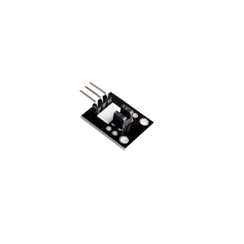


Broken Light Module:
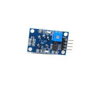
The Broken Light Module utilizes digital interface 13 along with LEDs to create a light-shielding warning system. It incorporates a simple circuit design, connecting the light shield sensor to digital interface 3. When the sensor detects a signal obstruction, the LED illuminates; otherwise, it remains off.
The photo interruption module functions by generating a signal when light is obstructed between the sensor’s openings. It comprises an optical emitter/detector at the front and two resistors (1 kΩ and 33 Ω) at the back.
Connection:
-
– (left) GND
-
+ (center) 5V
-
S (right) Pin 3
Specifications:
| Operating Voltage (V) | 5 |
|---|---|
| Interface (Digital) | 3 |
| Resistors Used | 1 kΩ and 33 Ω |
| Module Type | Photo Interruption Module |
Features:
-
Small size
-
Low Cost
-
Good performance
Package Includes:
-
1 x Broken Light Module
Broken Light Module Overview
The Broken Light Module is a photo interruption sensor designed to detect when an object blocks a beam of light between its emitter and detector. Operating at 5 V and interfaced via digital pin 3, it provides a simple LED-based warning system for collision detection, object counting, limit switching, and more.
Key Features of Broken Light Module
- Operating voltage of 5 V for compatibility with standard microcontroller boards
- Digital interface on pin 3 for easy signal reading
- Built-in LED indicator that lights up when the light path is interrupted
- Optical emitter/detector pair for reliable photo interruption sensing
- Integrated 1 kΩ and 33 Ω resistors to ensure stable current flow
- Genuine product with fast shipping from Zbotic
Applications and Use Cases
- Object detection in conveyor belt systems for automated sorting
- End-stop or limit switch in 3D printers and CNC machines
- Count bottles or items passing through a chute in packaging lines
- Obstacle detection for small robots and line-following vehicles
- Paper-jam detection in printers and copiers
- Light-shield alarm in safety interlock systems
How to Use Broken Light Module
Connect the module’s left pin to GND, the center pin to a 5 V supply, and the right pin (S) to digital interface 3 on your microcontroller. Position the emitter and detector openings face-to-face with a small gap; when an object blocks the light path, the onboard LED will illuminate and the digital output on pin 3 will go HIGH, allowing you to trigger interrupts or polling routines in your code.
Why Buy from Zbotic?
- Genuine Products: All items sourced from authorized distributors
- Fast Shipping: Orders ship within 24 hours with tracking (non backordered products)
- Free Shipping: Free delivery on qualifying orders
- COD Available: Cash on Delivery, UPI, cards, net banking
- Technical Support: Expert help for setup and troubleshooting
- Easy Returns: Hassle-free replacement for defective products
Frequently Asked Questions
How do I wire the Broken Light Module to an Arduino?
Connect the module’s GND pin to Arduino GND, the 5 V pin to Arduino 5 V, and the S (signal) pin to digital pin 3. Ensure the emitter and detector faces are aligned for proper beam interruption detection.
What does the LED indicator signify?
The onboard LED illuminates when the light beam between the emitter and detector is blocked. When the path is clear, the LED remains off and the digital output stays LOW.
Can I use this module with other microcontrollers?
Yes. Any microcontroller or development board supporting a 5 V digital input on pin 3 can read the Broken Light Module’s output. Ensure your I/O pin tolerates 5 V signals.

IR Proximity Sensor Calibration: Distance vs Voltage Curve
Infrared proximity sensors like the Sharp GP2Y series are widely used in robotics, obstacle avoidance, and automation projects...
Read More →
Analog Sensor Signal Conditioning: Op-Amp Circuit Designs
Most analog sensors produce output signals that are too small, offset, or noisy to be directly fed into...
Read More →
Rain Sensor Module: Detection, Calibration and Projects
Monsoon seasons across India bring months of unpredictable rainfall — and for electronics makers, that rainfall is an...
Read More →Technical Specifications
| SKU | AI2503 |
|---|---|
| Weight | 0.01 kg |
| Availability | In Stock |
Applications & Use Cases
The Broken Light Module Light/color Sensor is a versatile light/color sensor used across a wide range of applications including electronics projects, DIY builds, prototyping, and educational experiments.
Common use cases:
- Integrating into a custom electronics project
- Learning and experimenting with circuits
- Replacing or upgrading components in existing setups
This product is ideal for electronics enthusiasts, engineers, and students.
Technical Tip: Always verify voltage and current requirements before connecting to your circuit. Check datasheets for detailed specifications and pin configurations.
Shipping & Delivery
- Free shipping on orders above ₹999 across India
- Dispatched within 1-3 business days
- Expected delivery: 3-7 business days depending on location
- Secure packaging to ensure safe transit of electronic components


