
One of the most powerful features of a digital oscilloscope is also the one beginners find most confusing: the trigger system. Understanding oscilloscope trigger modes — especially edge, pulse width, and video triggers — transforms a scope from a confusing screen of moving lines into a precision measurement tool. This tutorial explains each trigger mode with practical examples so you can start capturing stable, meaningful waveforms immediately.
What Is an Oscilloscope Trigger and Why Does It Matter?
When an oscilloscope displays a waveform, it is constantly sampling the input signal and redrawing the screen. Without a trigger, each screen update starts at a different point in the signal’s cycle — the waveform appears to scroll or jump horizontally, making it impossible to study.
The trigger system solves this by defining a specific event in the signal that tells the oscilloscope: “start your acquisition from this moment.” Every subsequent acquisition begins at the same point in the waveform, so the display stays locked — the signal appears frozen and stable on screen even if it is actually a continuously cycling waveform.
The trigger does not change the signal or the measurement — it simply determines when the oscilloscope takes its snapshot. Getting triggering right is the difference between a stable, readable display and an unstable mess.
Key Trigger Controls on Any Scope
- Trigger Source: Which input channel (CH1, CH2, or external) to watch for the trigger event.
- Trigger Level: The voltage threshold the signal must cross to fire the trigger.
- Trigger Mode: Auto, Normal, or Single — controls when the scope waits for a trigger vs displays on its own.
- Trigger Type: Edge, Pulse, Video, Slope, and others depending on your scope model.
- Trigger Slope/Polarity: Rising edge, falling edge, or both.

9V Battery LCR-T4 12864 LCD Graphical Transistor Tester
Identify components quickly before probing with your oscilloscope. This LCR-T4 tester identifies transistors, capacitors, resistors, and diodes in seconds — essential for bench characterisation work.
Edge Trigger: The Foundation
Edge trigger is the default and most commonly used trigger type. It fires when the signal crosses a specified voltage threshold in a specified direction (rising or falling). Almost every oscilloscope measurement starts with edge trigger.
How to Set Up Edge Trigger
- Press the Trigger Menu button and select Edge as the trigger type.
- Select the source channel (CH1 for the channel your signal is connected to).
- Choose Rising edge (signal goes from low to high) or Falling edge (high to low). For most digital signals, rising edge is the natural choice.
- Adjust the trigger level. Most scopes have a dedicated trigger level knob. Set it to approximately mid-point of your signal’s amplitude — for a 3.3V logic signal, set it around 1.65V.
- Watch the scope display stabilise. If it does not stabilise, check that the trigger level is within the signal’s voltage range.
Auto vs Normal Trigger Mode with Edge Trigger
Auto mode: The scope displays a waveform even if no trigger event occurs. Good for initial setup and DC measurements, but the display may not be stable for periodic signals.
Normal mode: The scope waits indefinitely for a trigger event before updating the display. The screen holds the last captured waveform until the next trigger fires. Use this for cleaner, more stable captures of periodic signals.
Single mode: The scope waits for exactly one trigger event, captures a single screen of data, and stops. Essential for capturing one-shot events like power-on transients or button press glitches.
Practical Edge Trigger Examples
- Measuring PWM frequency: Trigger on the rising edge of a PWM signal. Measure the time between two consecutive rising edges using the time cursors.
- I²C/SPI clock capture: Trigger on the SCL/CLK rising edge to align data captures with the clock cycle.
- Power supply startup: Use single trigger mode on the rising edge of the output voltage to capture the startup transient.
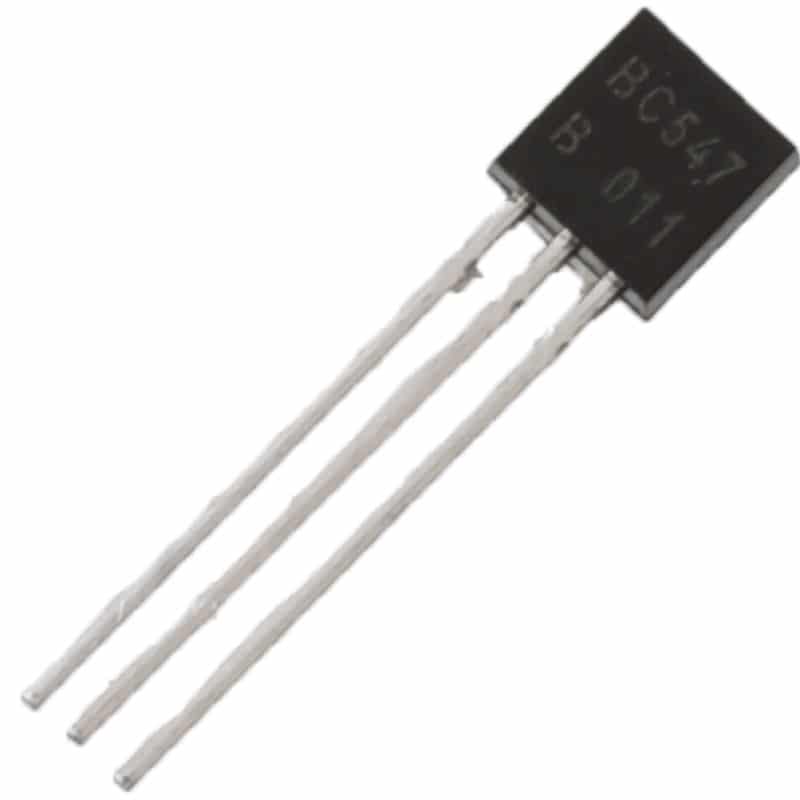
BC547 NPN 100mA Transistor TO-92 (Pack of 10)
A versatile general-purpose NPN transistor for switching and amplifier circuits. Probe the base, collector, and emitter with your oscilloscope’s edge trigger to study switching characteristics and saturation times.
Pulse Width Trigger: Catching Glitches
Pulse width trigger (also called Pulse trigger or Glitch trigger on some scopes) fires based on the width of a pulse rather than simply on an edge crossing. This makes it invaluable for finding signal integrity problems that edge trigger cannot catch.
How Pulse Width Trigger Works
You define a pulse width condition. For example: “trigger when there is a positive pulse narrower than 100 ns” or “trigger when a pulse is wider than 50 µs.” The scope then watches the signal continuously and fires only when a pulse matching your condition occurs — which could be rare, intermittent, or buried among thousands of normal pulses.
Pulse Width Trigger Conditions
- Less than (<): Trigger when a pulse is narrower than the specified width. Classic “glitch catch” mode.
- Greater than (>): Trigger when a pulse is wider than the specified width. Useful for catching timeout conditions.
- Equal to (=): Trigger when a pulse matches a specific width within a tolerance.
- Not equal (≠): Trigger when a pulse deviates from the normal width. Excellent for detecting intermittent protocol errors.
Practical Pulse Trigger Example: Finding a Spurious Reset
Imagine your microcontroller resets randomly but you cannot reproduce it reliably. Connect one oscilloscope channel to the RESET pin (active low). Set up a Pulse Width trigger for a negative pulse less than 1 µs. Switch to Single or Normal mode and leave the scope running. When the glitch occurs, the scope captures it — showing you the exact reset pulse width and helping you trace it back to a noise source or debounce issue.
This is something edge trigger simply cannot do, because the scope would trigger on every valid reset-and-release cycle just as readily as on the spurious spike. Pulse trigger gives you selectivity.
Video Trigger: Decoding Composite Video
Video trigger is a specialised trigger type designed for composite video signals (PAL, NTSC, or SECAM standards). Composite video has a complex structure with sync pulses, colour burst, and field blanking — making it impossible to trigger stably with a simple edge trigger.
Understanding Composite Video Sync
A composite video signal contains:
- Horizontal sync pulses: Short negative-going pulses (4.7 µs in PAL) that mark the start of each horizontal line.
- Vertical sync: A series of longer sync pulses that mark the start of each field (frame).
- Colour burst: A short burst of the colour subcarrier frequency (4.43 MHz for PAL, 3.58 MHz for NTSC).
- Video information: The luminance and chrominance content of the image.
Setting Up Video Trigger
- Select Video as the trigger type.
- Choose the video standard: PAL (used in India) or NTSC.
- Select trigger on: Field 1, Field 2, All Fields, or All Lines.
- For line-specific analysis, select “Line Number” and enter the line you want to examine.
- The scope will lock onto the video sync and display a stable waveform of the selected field or line.
When to Use Video Trigger
- Debugging composite video output from a microcontroller (Arduino TV-out projects).
- Analysing video signal quality from a camera module.
- Checking sync pulse timing in custom video generators.
- Measuring video signal amplitude and blanking levels.
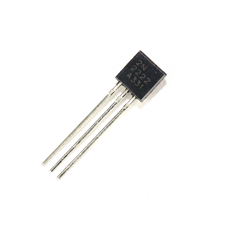
2N2222 NPN Transistor (Pack of 20)
A classic NPN general-purpose transistor ideal for switching circuits and simple amplifiers. Use your oscilloscope with edge trigger to study rise and fall times in 2N2222-based switching stages.
Slope and Runt Triggers (Advanced)
Slope Trigger
Slope trigger is similar to edge trigger but adds a time condition. It fires when a signal transitions from one level to another in a time interval that is less than, greater than, or equal to a specified duration. This lets you distinguish between a fast edge (clean digital signal) and a slow edge (degraded signal, capacitive loading, or cable problems).
Use case: Checking for excessive rise time on I²C SDA/SCL lines. The I²C specification requires a maximum rise time of 1000 ns for standard mode and 300 ns for fast mode. Slope trigger set to “rising edge slower than 1000 ns” will catch any slow rising edge — indicating a pull-up resistor value problem or excessive capacitance on the bus.
Runt Trigger
A runt pulse is one that crosses one threshold voltage but not the other — a pulse that “almost” happens but falls short. Runt trigger fires on these incomplete threshold crossings, which are a common sign of power supply noise, ground bounce, or signal integrity problems in high-speed digital systems.
Trigger Coupling and Noise Rejection
Trigger coupling controls what frequency components of the signal are used to determine trigger events. The options on most scopes include:
- DC Coupling: The full signal including DC component is used for triggering. Default setting for most measurements.
- AC Coupling: Blocks the DC component before the trigger comparator. Useful for triggering on the AC component of a signal with a large DC offset.
- LF Reject: High-pass filter before the trigger — rejects low-frequency components. Helps when a low-frequency interference is causing false triggers on a high-frequency signal.
- HF Reject: Low-pass filter before the trigger — rejects high-frequency noise. The most useful noise-rejection option when high-frequency noise on a power supply or digital signal is causing multiple triggers per cycle.
- Noise Reject: Adds hysteresis to the trigger comparator. A wider dead-band around the trigger level prevents noise around the threshold from causing multiple triggers. Use this first when you see a noisy, unstable trigger.
Practical Examples for Hobbyists
Example 1: Debugging an Arduino PWM Output
Connect CH1 to an Arduino pin outputting PWM. Set edge trigger, rising slope, trigger level at 1.65V. Read the frequency directly from the period measurement. Adjust duty cycle via analogWrite() and watch the pulse width change in real time.
Example 2: Capturing I²C Communication
Connect CH1 to SDA and CH2 to SCL. Set edge trigger source to CH2 (clock), rising edge. The scope locks to each clock edge. Use the zoom function to examine the data transitions relative to the clock. Look for setup and hold time violations.
Example 3: Power Supply Ripple Measurement
Connect CH1 to a DC power supply output using AC coupling on the vertical amplifier (not trigger coupling — set in the channel menu). This removes the DC level and shows only the AC ripple component. Use edge trigger with HF reject to get a stable ripple display. Measure peak-to-peak ripple voltage.
Example 4: Catching Intermittent I²C NACK
On an I²C bus with occasional communication failures, use pulse width trigger on the SDA line set to catch a pulse shorter than half a clock period. I²C ACK/NACK bits are one bit wide; if a NACK appears where an ACK is expected, the pulse pattern will be unusual. Leave scope in Normal trigger mode and wait for the error to occur.

10CM Male To Female Breadboard Jumper Wires 2.54MM – 40Pcs
Reliable jumper wires for connecting oscilloscope ground clips and test points on your breadboard or development board. Pack of 40 in multiple colours for easy signal identification.
Frequently Asked Questions
Why does my oscilloscope display show a rolling or scrolling waveform?
This means the trigger is not firing correctly. Either the trigger level is outside the signal’s voltage range, or the trigger source is set to the wrong channel. Check that the trigger level marker (usually a small triangle or arrow on the right side of the screen) is within the signal’s amplitude range.
When should I use Single trigger mode vs Normal mode?
Use Single mode for one-time events (power-on transients, button presses, fault conditions). Use Normal mode for repeating signals where you want a stable display while waiting for an event. Auto mode is best for initial signal verification before setting up a precise trigger.
What is the difference between trigger holdoff and trigger delay?
Holdoff prevents the trigger from re-arming for a specified time after a trigger event. This is useful for complex waveforms with multiple potential trigger points — it forces the scope to always trigger on the same point in the pattern. Trigger delay shifts the horizontal window relative to the trigger point, letting you look earlier or later in time from the trigger event.
Can I trigger on multiple channels simultaneously?
Most oscilloscopes trigger on a single source at a time. For multi-channel correlation, you choose one channel (usually the clock or sync signal) as the trigger source and observe the other channels in response. Some advanced scopes offer “pattern trigger” or “logic trigger” that conditions on a specific combination of states across multiple channels.
Why use a 10:1 probe for oscilloscope measurements?
A 10:1 probe reduces the capacitive loading on the circuit under test and extends the usable bandwidth. The probe’s tip capacitance is reduced from around 100 pF (1:1) to 12 pF (10:1). For signals above 1 MHz, always use a 10:1 probe. Remember to account for the 10x attenuation in your amplitude readings — most scopes allow you to set probe attenuation in the channel menu.
Master Your Oscilloscope Today
Understanding trigger modes unlocks the full diagnostic power of your oscilloscope. Practice these techniques on simple circuits first — an Arduino generating PWM, a 555 timer, or a simple RC oscillator — and you will quickly build the confidence to tackle complex debugging tasks. Shop Zbotic for the electronic components and test accessories you need to build your skills.


Add comment