
The MLX90614 is a factory-calibrated infrared thermometer sensor that enables truly contactless temperature measurement with Arduino — no physical contact with the object required. Developed by Melexis, this sensor measures the infrared radiation emitted by any object and converts it to a highly accurate temperature reading. From building a medical-grade fever screening system to monitoring motor temperatures, measuring food warmth without touching it, or creating a contactless industrial thermometer, the MLX90614 IR thermometer is the right tool for the job.
In this comprehensive guide, we cover the MLX90614 working principle, available variants, I2C communication with Arduino, complete code examples, emissivity calibration for different materials, and a gallery of real-world project applications. Whether you are a student, hobbyist, or professional engineer, this tutorial will give you everything you need to integrate the MLX90614 into your Arduino project.
1. How Infrared Temperature Measurement Works
All objects above absolute zero (−273.15°C) emit infrared radiation — electromagnetic waves in the 0.7 to 14 µm wavelength range. The intensity and spectral distribution of this radiation is directly related to the object’s temperature, governed by Planck’s law of blackbody radiation. Hotter objects emit more radiation and at shorter wavelengths.
An infrared thermometer sensor contains a thermopile — a device made from many thermocouple junctions arranged in series, sensitive to infrared radiation in a specific wavelength band. When infrared radiation from a target object hits the thermopile, it generates a tiny voltage proportional to the temperature difference between the thermopile and the target. The MLX90614 processes this voltage with its onboard signal conditioner and 17-bit ADC to produce a calibrated temperature output with ±0.5°C accuracy over a wide range.
Because this measurement is contactless, the sensor can measure:
- Moving objects (conveyor belt items, rotating parts) without friction or wear
- Hazardous materials (hot metals, acids, electricity-live components) from a safe distance
- Delicate objects (human skin, food, biological samples) without contamination
- Extremely hot surfaces that would destroy contact sensors
2. MLX90614 Overview and Variants
The MLX90614 family comes in several variants with different field-of-view (FOV) angles and interface options:
| Variant | FOV (half-angle) | Interface | Best For |
|---|---|---|---|
| MLX90614ESF-AAA | 35° (±17.5°) | I2C + PWM | General purpose, most common |
| MLX90614ESF-BAA | 35° | I2C + PWM | Extended temp range (-70°C to +380°C) |
| MLX90614ESF-DCI | 10° (±5°) | I2C | Narrow spot measurement at distance |
| MLX90614ESF-ACF | 70° | I2C | Body temperature (wide area) |
The most commonly available variant in India is the GY-906 module based on the MLX90614ESF-AAA with a 35° field of view — this is what most tutorials, including this one, focus on. The GY-906 module includes a 3.3V regulator, I2C pull-up resistors, and a convenient 4-pin header.
3. Specifications and Key Parameters
| Parameter | Value |
|---|---|
| Object Temperature Range | –70°C to +380°C (AAA variant) |
| Ambient Temperature Range | –40°C to +125°C |
| Accuracy (0–50°C ambient, object) | ±0.5°C |
| Resolution | 0.02°C |
| Field of View (AAA) | 35° (half-angle ±17.5°) |
| Communication | I2C (SMBus protocol) + PWM |
| I2C Address | 0x5A (default, reprogrammable) |
| Supply Voltage | 3V (chip); GY-906 module: 3.3V–5V |
| Supply Current | ~1.5 mA (operating) |
| Sleep Current | ~2.5 µA |
| Response Time | ~100 ms (typical) |
The 0.02°C resolution and ±0.5°C accuracy over the 0–50°C range makes the MLX90614 suitable for medical applications like fever screening — where 0.3°C differences matter for detecting a temperature of 37.5°C vs 37.2°C. Accuracy decreases slightly at temperature extremes outside this range.
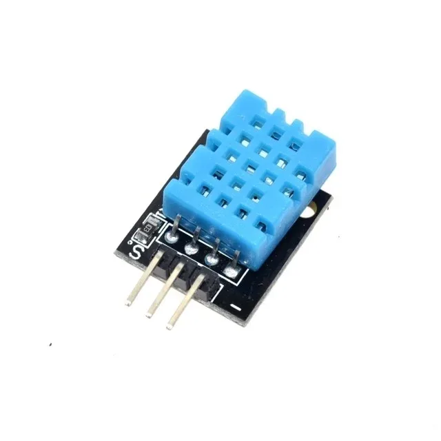
DHT11 Digital Relative Humidity and Temperature Sensor Module
Complement the MLX90614 contactless thermometer with a DHT11 for ambient humidity monitoring — ideal for HVAC systems and weather stations.
4. Wiring MLX90614 to Arduino
The GY-906 MLX90614 module has a simple 4-pin interface:
| GY-906 Pin | Arduino Uno/Nano Pin |
|---|---|
| VCC | 5V (module has onboard 3.3V regulator) |
| GND | GND |
| SCL | A5 |
| SDA | A4 |
Important wiring notes:
- The MLX90614 chip itself operates at 3V. The GY-906 module includes a 3.3V LDO regulator and level-shifted I2C lines — making it safe to use with 5V Arduinos.
- The MLX90614 uses SMBus (System Management Bus), which is largely compatible with standard I2C at 100 kHz but has some subtle differences. The Adafruit library handles this transparently.
- If connecting the bare chip (not GY-906 module), add 4.7kΩ pull-up resistors on both SDA and SCL lines to 3.3V.
- Do NOT connect the bare MLX90614 chip to 5V — it operates at 3V maximum. The GY-906 module’s regulator handles this.
5. Installing the Adafruit MLX90614 Library
Open the Arduino IDE, go to Sketch → Include Library → Manage Libraries, search for “Adafruit MLX90614” and install the library. Also install the Adafruit BusIO library if prompted (required dependency).
The Adafruit MLX90614 library provides a clean API for reading both object temperature and ambient temperature in Celsius, Fahrenheit, or Kelvin, as well as functions for reading and writing the EEPROM configuration (including emissivity and I2C address).
6. Basic Arduino Code: Reading Object and Ambient Temperature
#include <Adafruit_MLX90614.h>
#include <Wire.h>

Adafruit_MLX90614 mlx = Adafruit_MLX90614();

void setup() {
  Serial.begin(9600);
  if (!mlx.begin()) {
    Serial.println("MLX90614 not found! Check wiring.");
    while (1);
  }
  Serial.print("Emissivity: ");
  Serial.println(mlx.readEmissivity());
}

void loop() {
  Serial.print("Ambient = ");
  Serial.print(mlx.readAmbientTempC());
  Serial.print(" *C  |  ");

  Serial.print("Object = ");
  Serial.print(mlx.readObjectTempC());
  Serial.println(" *C");

  // Fever detection example:
  float bodyTemp = mlx.readObjectTempC();
  if (bodyTemp >= 37.5) {
    Serial.println("WARNING: Elevated temperature detected!");
  }

  delay(500);
}
Upload this sketch and open the Serial Monitor at 9600 baud. You will see two temperature readings:
- Ambient temperature: The temperature of the sensor itself and its immediate surroundings — useful for compensation and as a secondary environment sensor.
- Object temperature: The contactless temperature of whatever the sensor is aimed at.
For human body temperature measurement, the sensor should be positioned 3–5 cm from the forehead or wrist. At this distance with the 35° FOV sensor, the measurement spot diameter is approximately 2–3 cm — comfortably covering the area needed for skin temperature reading.
7. Understanding and Setting Emissivity
Emissivity is the most misunderstood aspect of infrared thermometry. It measures how efficiently an object emits thermal radiation compared to a perfect blackbody (emissivity = 1.0). The MLX90614’s default emissivity is 1.0, which is appropriate for skin, organic materials, and most painted surfaces. However, for metallic or highly reflective surfaces, using the wrong emissivity setting causes significant temperature errors.
Common material emissivities:
| Material | Emissivity |
|---|---|
| Human skin | 0.95–0.98 |
| Flat black paint | 0.95 |
| Wood | 0.90–0.95 |
| Concrete, brick | 0.90–0.95 |
| Polished aluminium | 0.04–0.06 |
| Oxidised steel | 0.80–0.90 |
| Polished copper | 0.02–0.05 |
| PCB (green) | 0.85–0.90 |
| Water | 0.95–0.98 |
Setting emissivity in code (stored in EEPROM — survives power cycles):
#include <Adafruit_MLX90614.h>
Adafruit_MLX90614 mlx = Adafruit_MLX90614();

void setup() {
  Serial.begin(9600);
  mlx.begin();

  // Read current emissivity
  double currentE = mlx.readEmissivity();
  Serial.print("Current emissivity: ");
  Serial.println(currentE);

  // Set new emissivity for oxidised steel (example)
  // WARNING: This writes to EEPROM — limited write cycles!
  // Only do this once during setup, not in a loop!
  // mlx.writeEmissivity(0.85);
  // Serial.println("Emissivity updated. Power cycle the sensor.");
}

void loop() {
  Serial.print("Object Temp: ");
  Serial.println(mlx.readObjectTempC());
  delay(500);
}
Important: The EEPROM write capability is limited (approximately 10,000 write cycles). Only write emissivity during initial configuration, not in the main loop. After writing, power cycle the sensor for the change to take effect.

LM35 Temperature Sensors
Use the LM35 as a precision ambient temperature reference alongside the MLX90614 — cross-validate readings and improve emissivity calibration accuracy.
8. Effect of Distance and Field of View
The MLX90614’s 35° field of view means it “sees” a cone of IR radiation rather than a precise point. At any given distance, the sensor averages the temperature across an elliptical spot. The spot size formula:
Spot diameter = 2 × distance × tan(FOV half-angle)
For the AAA variant (FOV = ±17.5°):
- At 1 cm distance: spot ≈ 6 mm diameter
- At 5 cm distance: spot ≈ 31 mm diameter
- At 10 cm distance: spot ≈ 63 mm diameter
- At 30 cm distance: spot ≈ 19 cm diameter
Key implications:
- The target object must be larger than the spot size for an accurate reading — if the spot extends beyond the object, background temperature contaminates the reading
- For body temperature (forehead/wrist), 3–5 cm distance gives a 2–3 cm spot — ideal coverage
- For measuring a small component like an IC chip, get as close as possible to maximise spot coverage of the target
- For measuring a large area (oven interior, radiator), distance doesn’t matter much as long as the sensor “sees” the target
9. Low Power Sleep Mode
For battery-powered projects, the MLX90614 supports a sleep mode that draws only ~2.5 µA. Wake-up is triggered by an SMBus command or by toggling the SCL line:
#include <Adafruit_MLX90614.h>
Adafruit_MLX90614 mlx = Adafruit_MLX90614();

void setup() {
  Serial.begin(9600);
  mlx.begin();
}

void loop() {
  // Read temperature
  float temp = mlx.readObjectTempC();
  Serial.print("Object: "); Serial.println(temp);

  // Enter sleep mode (saves ~1.5 mA)
  mlx.sleep();

  // Sleep Arduino for 7 seconds
  delay(7000);

  // Wake sensor (send wake command on I2C)
  // Must re-initialize I2C and wait ~250ms for sensor to stabilize
  pinMode(A4, OUTPUT);      // SDA
  digitalWrite(A4, HIGH);
  delay(50);
  Wire.begin();
  mlx.begin();
  delay(300);  // Wait for sensor warmup after wake
}
Combined with Arduino’s own sleep modes (using the LowPower library), a battery-powered temperature monitoring system can achieve years of operation on a small LiPo battery when sampling only once per minute.
10. Real-World Project Applications
Contactless Fever Screening Station
The most prominent post-COVID application. Mount the MLX90614 in a stand at forehead height, display temperature on an LCD, and trigger a green/red LED + buzzer for pass/fail. Add a servo to prevent entry if temperature exceeds a threshold. Use the wide-FOV variant for easier alignment, or the standard 35° variant at a fixed 5 cm distance.
Motor and Bearing Temperature Monitoring
Overheating bearings and motor windings are among the most common causes of industrial equipment failure. Mount the MLX90614 near critical bearings and trigger alarms when temperature exceeds safe limits. The contactless measurement means no risk of damaging temperature sensors from vibration or rotating shaft contact.
PCB Thermal Analysis
Identify hot spots on circuit boards by scanning the MLX90614 across the board surface. This is an affordable alternative to professional thermal cameras — while the spatial resolution is much lower (single measurement point vs thousands of pixels), it can identify dramatically overheating components like voltage regulators, MOSFETs, or shorted traces.
Food Temperature Control
Monitor pizza oven surface temperature, verify cooking temperature of frying oil, or check if baby food is at the right temperature — all without probe contact. For food safety, the MLX90614 at ε=0.95 reads metal cookware surfaces accurately enough for practical cooking guidance.
3D Printer Bed Levelling Aid
Measure the heated bed temperature at multiple points to verify uniformity before printing. A non-uniform heated bed causes warping and adhesion failures. Scanning the MLX90614 across the bed surface maps temperature distribution without the risk of physical probe contact scratching the bed surface.
Smart HVAC Thermostat
Measure human presence and skin temperature for comfort-based HVAC control. Unlike ambient air thermostats, an IR sensor can detect the actual thermal comfort of occupants — adjusting cooling or heating based on body temperature rather than delayed air temperature response.

DS18B20 Programmable Resolution Temperature Sensor
Pair the MLX90614 contactless sensor with DS18B20 for simultaneous IR and contact temperature measurement — great for cross-validation and process monitoring.
11. Troubleshooting Common Issues
Sensor Not Found on I2C (0x5A)
Run the Arduino I2C scanner sketch to see what address the sensor appears on. If nothing appears, check SDA/SCL connections (A4/A5 on Uno). Verify the module has power (LED on GY-906 confirms power). The MLX90614 I2C address can be reprogrammed to any address in the 0x00–0x7F range — if a previous user changed it, you may need to scan all addresses. Note: some very cheap clones have reliability issues — try reducing I2C bus speed to 50 kHz if at 100 kHz causes issues.
Readings Are Too Low or Too High for Known Objects
Almost certainly an emissivity mismatch. Verify the current emissivity setting (mlx.readEmissivity()). The default is 1.0, correct for organic materials. For polished metal surfaces, emissivity may be as low as 0.05 — reading a polished aluminium heatsink with emissivity 1.0 will give a wildly inaccurate reading because you are measuring reflected ambient radiation rather than the object’s own emission. Apply matte black paint or black electrical tape to the measurement spot for consistency.
Temperature Reading is Actually the Ambient Air Temperature
The sensor needs a clear line of sight to the target. If the target is too small, too far away, or if glass/plastic is between sensor and target (these materials block IR), the sensor reads surrounding ambient temperature. Note: glass is opaque to the 8–14 µm IR wavelength range, unlike visible light — you cannot measure temperature through a glass window.
Readings Fluctuate Rapidly
This is normal for the MLX90614 — the 100 ms response time means readings can change quickly as the sensor pans across different temperature objects. For stable readings, point the sensor at the target, wait 200–500 ms for it to stabilise, then take an average of several readings. Avoid air currents near the sensor (they cool the thermopile and shift readings).
Can’t Write Emissivity — I2C Error
Writing to MLX90614 EEPROM requires erasing the current value first (write 0x0000 to the emissivity register), waiting 5 ms, then writing the new value. The Adafruit library handles this automatically. If writes fail, ensure you are using the genuine Adafruit library version 2.x or later. Also, note that write cycles are limited to ~10,000 — if the sensor has been written to many times, EEPROM writes may start failing.
12. Frequently Asked Questions
Can the MLX90614 measure temperatures through glass or plastic?
No. Glass, plastic, and most transparent materials are opaque to the 8–14 µm infrared wavelengths the MLX90614 detects, even though they appear transparent to visible light. This is why you can feel heat through a glass window even though it blocks most far-infrared radiation. To measure an object behind glass or plastic, you would need to use a germanium optical window (transmissive to far-IR) or remove the barrier. Standard window glass transmits only about 1% of the far-infrared wavelengths used for temperature measurement.
How accurate is the MLX90614 for body temperature measurement?
The MLX90614 is specified at ±0.5°C accuracy in the 0–50°C range, which includes the body temperature range (35–42°C). For forehead temperature, the sensor reads slightly lower than core body temperature (typically 0.5–1°C lower, depending on room temperature and ambient conditions). This is normal — clinical forehead thermometers apply a correction factor. For medical-grade screening, use the sensor at a fixed 3–5 cm distance in a temperature-controlled environment, and add a compensation factor based on ambient temperature. The sensor is suitable for screening (detecting elevated temperatures) but not for precise clinical diagnosis.
Can I change the MLX90614’s I2C address?
Yes. The I2C address (default 0x5A) is stored in EEPROM and can be changed to any address in 0x01–0x7E range. This allows multiple MLX90614 sensors on the same I2C bus. The address change procedure requires writing to the EEPROM SA register. Once changed, the new address is permanent until changed again. Since only one MLX90614 at address 0x5A can be on the bus at a time during reprogramming, address changes should be done one sensor at a time. Some library functions support specifying a non-default I2C address in the begin() call.
What is the difference between MLX90614 and MLX90615?
The MLX90615 is a newer, smaller successor to the MLX90614 in a TO-46 package. It has similar accuracy and temperature range but features a smaller footprint and reduced power consumption. The MLX90615 uses slightly different EEPROM register addresses in its configuration. The MLX90614 remains more common in maker communities due to wider library support and greater module availability in India. For new designs, the MLX90615 may be preferable for space-constrained applications.
Why does the MLX90614 read differently in summer vs winter?
The MLX90614’s thermopile measures the temperature difference between the target object and the sensor’s own thermopile junction. When the ambient temperature (and thus the sensor temperature) changes significantly, the baseline for this differential measurement shifts. The sensor’s internal ambient temperature compensation corrects for this over its rated range, but extreme ambient temperature changes (e.g., sensor stored in a cold AC room, then immediately used outdoors in 40°C heat) can take several minutes for the sensor to thermally stabilise. Allow 5–10 minutes warm-up time after significant ambient temperature changes before taking critical measurements.
Conclusion
The MLX90614 is a remarkable piece of engineering — factory-calibrated to ±0.5°C accuracy, covering an enormous temperature range from –70°C to +380°C, with a simple I2C interface that any Arduino beginner can use within minutes of unboxing. Its contactless operation makes it irreplaceable in applications where touch is impossible, impractical, or unsafe.
The key to accurate MLX90614 measurements: understand emissivity and set it correctly for your target material, maintain a consistent sensing distance appropriate to your target size, allow adequate thermal stabilisation time, and average multiple readings for best accuracy. With these practices in place, the MLX90614 delivers professional-grade infrared temperature measurement at an accessible price point.
From a simple fever screener to a sophisticated industrial temperature monitoring system, the MLX90614 paired with Arduino offers a powerful, affordable platform for contactless temperature applications in any domain.


Add comment