
An IoT smart energy monitor with ESP32 is one of the most impactful home automation projects you can build. With electricity bills rising across India and smart metering becoming more common, building your own non-invasive energy monitor gives you real-time insight into how much power your home is consuming — appliance by appliance. This project uses affordable current sensors and the ESP32’s Wi-Fi capability to stream live power data to your phone or a cloud dashboard.
In this guide, we cover the hardware selection, circuit design, Arduino code, and cloud integration needed to build a fully functional smart energy monitor from scratch — all with components available in India.
How Non-Invasive Energy Monitors Work
Unlike traditional energy meters that require cutting into mains wiring, a non-invasive energy monitor uses a Current Transformer (CT) sensor that clips around a live wire. The changing magnetic field created by the AC current induces a small proportional current in the CT’s secondary coil, which the microcontroller measures to calculate the actual current flowing through the wire.
Combined with knowledge of the mains voltage (230V AC at 50 Hz in India), the microcontroller can calculate:
- Apparent Power (VA): Vrms × Irms
- Real Power (W): Vrms × Irms × Power Factor
- Energy Consumption (kWh): Real Power integrated over time
The most popular CT sensor for DIY energy monitors in India is the YHDC SCT-013 series, which comes in variants rated for 30A, 100A, and 200A — suitable for monitoring individual circuits or the entire home mains.
For accurate power factor measurement (important for inductive loads like motors, compressors, and fluorescent lights), you need a voltage reference. This can be done with a small 9V AC transformer connected to another ADC pin, allowing the ESP32 to measure both voltage and current waveforms simultaneously and calculate the true phase angle between them.
Components Required
Here is everything you need to build a complete IoT energy monitor:
| Component | Specification | Purpose |
|---|---|---|
| ESP32 Dev Board | NodeMCU-32S or similar | Main microcontroller with Wi-Fi |
| CT Sensor | SCT-013-030 (30A) or SCT-013-100 (100A) | Non-invasive current measurement |
| Burden Resistor | 33Ω for 30A version | Converts CT current to measurable voltage |
| Voltage Divider | 2× 10kΩ resistors | Biases CT output to mid-rail |
| Capacitor | 10µF electrolytic | Filters bias voltage |
| 3.5mm Audio Jack | Female stereo | CT sensor connector |
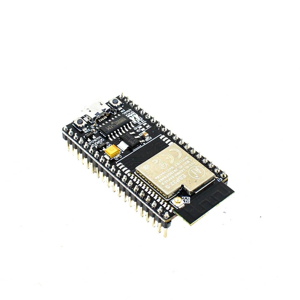
Ai Thinker NodeMCU-32S ESP32 Development Board – IPEX Version
The heart of your energy monitor. Dual-core 240MHz processor with 12-bit ADC channels, built-in Wi-Fi and Bluetooth — ideal for real-time power measurement and cloud upload.
Circuit Design and Wiring
The ESP32’s ADC input accepts 0-3.3V. The CT sensor output is a small AC current centred around 0V. To interface it with the ESP32’s ADC, you need to:
- Add a burden resistor across the CT output to convert current to voltage.
- Create a voltage bias at VCC/2 (1.65V) using two equal resistors as a voltage divider, so the AC waveform oscillates around mid-rail instead of going negative.
- Add a decoupling capacitor to stabilise the bias voltage.
Connect the CT sensor output (via a 3.5mm jack) to the bias circuit, and the junction of the burden resistor and bias resistors to GPIO 34 (or any ADC1 channel) of the ESP32. GPIO 34 is recommended because it is input-only and has no internal pull-up/pull-down that could interfere with ADC readings.
Important Safety Note
The CT sensor is the only component that contacts your home’s mains wiring. All other components operate at safe low voltage. Never remove the CT sensor from the wire while it is open-circuit (without the burden resistor connected) — the voltage can spike to dangerous levels. Always connect the burden resistor before clamping the CT around a live wire.
Arduino Code for Power Measurement
We will use the excellent EmonLib library, which handles all the signal processing for current and power calculation. Install it from the Arduino Library Manager by searching for “EmonLib”.
#include <WiFi.h>
#include <EmonLib.h>
#include <time.h>

EnergyMonitor emon1;

const char* ssid     = "YourWiFiSSID";
const char* password = "YourWiFiPassword";

// India mains voltage
const float MAINS_VOLTAGE = 230.0;

// Calibration value — adjust based on your CT sensor and burden resistor
// For SCT-013-030 with 33Ω burden: calibration ≈ 111.1
const double CALIBRATION = 111.1;

void setup() {
  Serial.begin(115200);

  // Initialize CT sensor on ADC pin 34
  emon1.current(34, CALIBRATION);

  // Connect to Wi-Fi
  WiFi.begin(ssid, password);
  while (WiFi.status() != WL_CONNECTED) {
    delay(500);
    Serial.print(".");
  }
  Serial.println("nWi-Fi connected!");

  // Sync NTP time
  configTime(19800, 0, "pool.ntp.org");
}

void loop() {
  // Read RMS current (number of samples, crossings)
  double Irms = emon1.calcIrms(1480);

  // Calculate apparent power
  double apparentPower = Irms * MAINS_VOLTAGE;

  // Get timestamp
  struct tm t;
  getLocalTime(&t);
  char timeStr[20];
  strftime(timeStr, sizeof(timeStr), "%H:%M:%S", &t);

  Serial.printf("[%s] I=%.3fA  P=%.1fVAn",
                timeStr, Irms, apparentPower);

  delay(2000);
}
Calibrating Your CT Sensor
The calibration value depends on your specific CT sensor and burden resistor. To calibrate accurately:
- Connect a known load (e.g., a 100W incandescent bulb — draw should be ≈0.435A at 230V)
- Use a clamp meter to measure the actual current
- Adjust the calibration constant in the sketch until your ESP32 reading matches the clamp meter
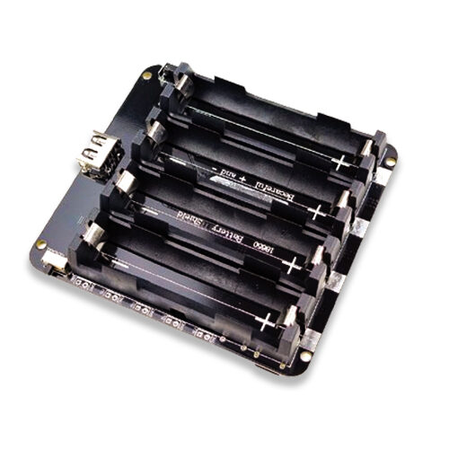
4×18650 Battery Shield for Arduino/ESP32/ESP8266
Power your ESP32 energy monitor with a reliable lithium battery shield — provides uninterrupted monitoring even during power cuts, with an on/off switch for convenience.
Sending Data to a Cloud Dashboard
Raw serial output is useful for development, but a proper IoT energy monitor should send data to a cloud platform where you can view graphs, set alerts, and analyse trends. Popular free options for Indian makers include:
Blynk
Blynk is beginner-friendly and has a free tier that is sufficient for a single energy monitor. Add the Blynk library, create a project on the Blynk app, and use Blynk.virtualWrite(V1, apparentPower) to push data every few seconds. The app displays a live gauge and historical graph.
ThingSpeak (MathWorks)
ThingSpeak is free for up to 4 channels and stores up to 3 million data points. Use the ESP32’s HTTPClient to POST data to your channel’s API endpoint every 15 seconds. ThingSpeak also supports MATLAB-powered analytics for deeper insight into your consumption patterns.
MQTT + Node-RED + Grafana
For a more advanced, self-hosted setup, install Mosquitto MQTT broker and Node-RED on a Raspberry Pi on your home network. The ESP32 publishes power readings to an MQTT topic, Node-RED subscribes and stores them in InfluxDB, and Grafana provides beautiful time-series dashboards. This approach gives you complete data ownership.
// Example: Send to ThingSpeak
#include <HTTPClient.h>

const String apiKey = "YOUR_THINGSPEAK_API_KEY";

void sendToThingSpeak(float watts, float amps) {
  if (WiFi.status() == WL_CONNECTED) {
    HTTPClient http;
    String url = "http://api.thingspeak.com/update?api_key=" + apiKey
                 + "&field1=" + String(watts)
                 + "&field2=" + String(amps);
    http.begin(url);
    int code = http.GET();
    http.end();
  }
}
Calculating Cost Savings and ROI
Once you have a week of energy data, you can start identifying high-consumption appliances and peak usage times. In India, most residential consumers are on a slab-rate tariff where the first 100 units (kWh) per month are cheaper and subsequent units are billed at a higher rate.
Here is a simple calculation to add to your dashboard:
- Daily kWh: Sum all watt-hours readings and divide by 1000
- Monthly kWh: Daily kWh × 30
- Estimated monthly bill: Based on your state’s DISCOM tariff (e.g., ₹6/unit in Maharashtra for 101-300 units)
Many users report finding phantom loads from devices left on standby — TVs, set-top boxes, desktop computers, and phone chargers. Eliminating standby power on just a few devices can save ₹100-500 per month on your electricity bill.
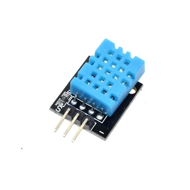
DHT11 Digital Relative Humidity and Temperature Sensor Module
Add temperature and humidity monitoring alongside your energy data — correlate AC usage with ambient conditions to optimise cooling schedules and save on electricity bills.
Advanced Features to Add
Once your basic monitor is working, consider these enhancements to make it truly smart:
Multi-Circuit Monitoring
The ESP32 has multiple ADC channels (ADC1: GPIO 32-39). You can connect up to 4-6 CT sensors simultaneously to monitor individual circuits — kitchen, bedroom, AC, water heater — each independently. This gives you a detailed breakdown of per-circuit consumption rather than just whole-home data.
Automatic Alerts
Set thresholds in your ESP32 code to trigger alerts if power consumption exceeds a limit (e.g., above 3000W for more than 10 minutes). Send an alert via Telegram bot, push notification through Blynk, or an email via SMTP. This can catch faulty appliances, forgotten ovens, or unusual consumption.
Monthly Bill Prediction
Track cumulative kWh since the 1st of the month in SPIFFS or EEPROM. Apply your local DISCOM’s tariff schedule to calculate a predicted bill. Display this on an OLED screen or send a weekly WhatsApp update via a webhook.
Integration with Home Assistant
If you run Home Assistant on a Raspberry Pi, add the ESP32 energy monitor as an MQTT sensor. Home Assistant’s Energy Dashboard can then show your home’s consumption history alongside solar production data, giving you a complete energy overview in one place.
Frequently Asked Questions
Is it safe to build a DIY energy monitor?
Yes, when done correctly. The CT sensor is the only component near mains voltage, and it is specifically designed for safe, non-invasive clamping. The ESP32 circuit operates entirely at 3.3V/5V. However, always turn off the MCB and circuit breaker before opening your distribution board, and if you are not comfortable working with electrical panels, consult a licensed electrician to clamp the CT sensor for you.
How many circuits can one ESP32 monitor?
The ESP32 has 6 usable ADC1 channels (GPIO 32-39). However, ADC2 channels are shared with Wi-Fi and cannot be used reliably when Wi-Fi is active. So practically you can monitor 4-6 circuits simultaneously with one ESP32, using ADC1 channels only.
What is the accuracy of a CT sensor energy monitor?
A well-calibrated SCT-013 setup typically achieves ±2-3% accuracy, which is comparable to many commercial energy monitors. For purely resistive loads (heaters, incandescent bulbs), accuracy is higher. For inductive loads (motors, compressors), you need voltage measurement to accurately calculate real power and power factor.
Can I monitor a 3-phase connection?
Yes, but you need one CT sensor per phase (3 total) and ideally a voltage reference per phase as well. The ESP32 has enough ADC channels for this. Libraries like EmonLib can handle multi-phase calculations with some customisation.
Build Your Smart Energy Monitor Today
Get all the ESP32 boards, sensors, and modules you need for your IoT energy monitoring project at Zbotic — fast shipping across India.


Add comment