
Picking the wrong motor driver is one of the most common and expensive mistakes in robotics. Too weak a driver and it overheats and dies within minutes. Too large and you waste money, PCB space, and introduce unnecessary quiescent current drain on battery-powered builds. This formula-based guide gives you a systematic method to select the right driver for any DC motor you have on hand — from tiny 130-size toy motors to heavy-duty 24 V gear motors drawing 20 A.
Reading Your DC Motor Specifications
Before selecting a driver you need four numbers from your motor’s datasheet or from measurement:
- Rated voltage (Vrated): The supply voltage at which the motor is designed to run continuously. Operating significantly above this reduces motor life; operating below reduces torque and speed proportionally.
- No-load current (INL): Current drawn at the rated voltage with no mechanical load. This is typically 10–20% of rated current and represents friction and windage losses inside the motor.
- Rated current (Irated): Current at rated torque and speed. Some datasheets call this the operating current or full-load current.
- Stall current (Istall): Current drawn when the motor shaft is held stationary. This is the worst-case current the motor will ever draw and the number that sizes your driver. Stall current = Vrated ÷ Rwinding.
If you do not have a datasheet — very common with unmarked DC motors from kits — measure the winding resistance with a multimeter set to Ohms. Divide the supply voltage by this resistance to estimate stall current: Istall = V / R.
For example: a motor reads 2.8 Ω at 12 V supply gives Istall = 12 / 2.8 = 4.3 A. Your driver must survive 4.3 A peak.
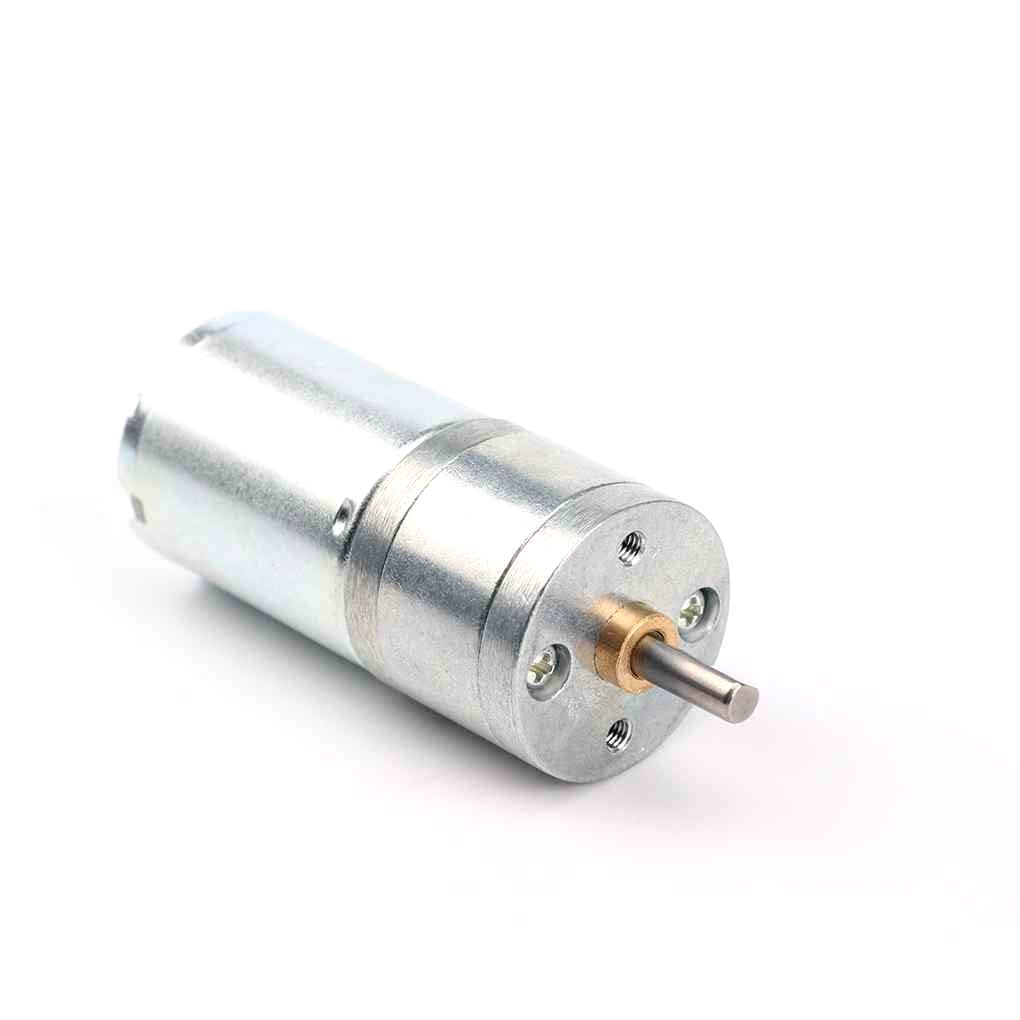
25GA-370 12V 12RPM DC Reducer Gear Motor
A well-specced 12 V gear motor with published datasheet current ratings — ideal for practising the driver selection formulas in this guide.
Stall Current: The Critical Rating
Stall current is the worst case your driver will ever face, and it happens every time the motor starts from rest, every time it hits a physical obstruction, and during any sudden direction reversal. A driver that cannot survive stall current — even for a few hundred milliseconds — will fail in normal operation.
The relationship between stall current and driver sizing uses a derating factor. You should never run a driver continuously at its absolute maximum current rating. Thermal resistance, ambient temperature, PCB copper area, and the fact that datasheets use pulse conditions to measure peak ratings all mean you need headroom.
Rule of thumb: size the driver for 2× the stall current of the motor.
Formula: I_driver_continuous ≥ I_stall_motor × 1.5 (minimum) to 2× (recommended)
At 2× headroom, the driver operates comfortably within its linear thermal region even during repeated stall events. At 1.5× it will survive but may require active cooling in hot environments.
Do not confuse peak current with continuous current in driver datasheets. A driver rated at 5 A peak / 2 A continuous will not survive a 4 A stall current for more than a second or two before the thermal protection cuts in — or worse, before it silently degrades and fails weeks later.
Voltage Rating and Supply Headroom
The driver’s maximum voltage rating must exceed your supply voltage with margin for transients. When a motor decelerates rapidly or when PWM switches the inductive motor winding off, the collapsing magnetic field generates a voltage spike (back-EMF) that can easily be 20–50% above the supply rail.
Formula: V_driver_max ≥ V_supply × 1.3 (minimum)
Practical examples:
- 6 V supply → driver rated at ≥ 8 V (use a 10 V or 15 V rated driver)
- 12 V supply → driver rated at ≥ 16 V (use a 24 V or 36 V rated driver)
- 24 V supply → driver rated at ≥ 32 V (use a 40 V or 50 V rated driver)
All good H-bridge drivers include freewheeling diodes (either internal or as a Schottky diode recommendation in the datasheet) to clamp back-EMF spikes. Always verify that the driver you choose has these diodes. A driver without freewheeling diodes (or without them specified in the BOM) will fail rapidly with inductive motor loads.
Continuous vs Peak Driver Current
Driver datasheets list current in multiple ways and conflating them is the most common sizing mistake:
Absolute maximum current: The current at which the driver will be instantly destroyed. This is a hard limit with zero margin. Never design to this number.
Peak current (pulsed): Tested at a short duty cycle (often 10 ms on / 10 s off in lab conditions). This is what the driver can handle for very brief transients, not for sustained stall conditions.
Continuous current (with or without heatsink): The current at which the driver reaches its maximum junction temperature in thermal equilibrium. This is the number to design around. Note that datasheet conditions assume 25°C ambient — inside a hot enclosure on a summer day, derate by 10–20%.
Comparison of popular drivers by continuous current:
- L293D: 600 mA continuous, 1.2 A peak (per channel)
- L298N: 2 A continuous, 3 A peak (per channel)
- L9110S: 800 mA continuous, 1.5 A peak (per channel)
- DRV8833: 1.5 A continuous, 2 A peak (per channel)
- MX1508: 1.5 A continuous, 2.5 A peak
- BTS7960: 43 A continuous, 65 A peak (half-bridge pair for one channel)
- TB6612FNG: 1.2 A continuous, 3.2 A peak (per channel)
Popular Driver ICs Compared
Choosing between drivers involves more than just current rating. Here is a practical comparison of the most common options available to Indian makers:
L293D — Entry Level
The L293D is a bipolar (non-MOSFET) H-bridge with very high on-resistance (≈3.5 Ω total), meaning it drops almost 2 V at 600 mA — so a 5 V motor only gets ≈3 V. Combined with no internal freewheeling diodes (the L293D, not L293DD, lacks them), this driver is fine for learning but not for production. Use it for motors under 200 mA with a 9–12 V supply to maintain motor voltage after dropout.
L298N — Workhorse for 2 A Motors
The L298N is still bipolar but can do 2 A per channel and 4 A bridge for one motor. Its large dropout voltage (≈2.7 V at 2 A) is a disadvantage: an L298N on a 7.4 V battery delivers only ≈4.7 V to the motor. Use it for 12 V systems where the 2.7 V drop is proportionally smaller. Always add a heatsink — the plastic TO-220 package dissipates heat poorly without one.
L9110S — Budget Dual Driver
The L9110S (or HG7881) is a CMOS H-bridge with much lower on-resistance than the L293D (≈0.8 Ω), making it far more efficient. At 800 mA continuous it works well for small gear motors in robot chassis. Its only drawback is a maximum supply of 12 V. Extremely popular for budget robot kits because of its tiny footprint and low cost.
DRV8833 / TB6612FNG — Mid-Range MOSFET Drivers
Both use MOSFET H-bridges with low Rds(on) (typically 0.3–0.6 Ω), giving very low voltage drop even at 1–2 A. The DRV8833 adds overcurrent and thermal protection. These are the sweet spot for 3.7–12 V systems in the 1–2 A range — clean efficiency, small PCB footprint, and reliable protection features.
BTS7960 — High Current Applications
The BTS7960 is a single half-bridge capable of 43 A continuous. Two BTS7960 chips make one full H-bridge for very large motors. Used in e-bike controllers, heavy robotics, and automotive applications. Includes overcurrent protection, overvoltage protection, and thermal shutdown. For 24 V, 10 A+ applications it is the go-to solution.
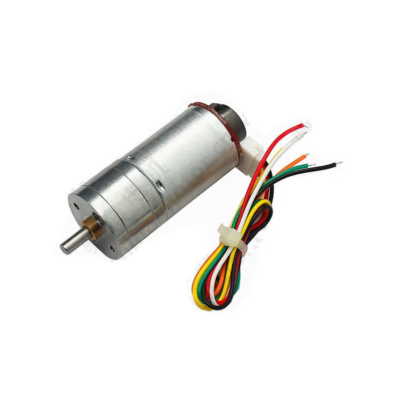
25GA-370 12V 12RPM DC Reducer Gear Motor with Encoder
Gear motor with quadrature encoder for closed-loop speed control. Pair with a DRV8833 or TB6612FNG for precise position-controlled robotics.
Thermal Management and Heat Dissipation
Even a correctly sized driver will overheat without adequate heat management. Power dissipated in the driver is:
P_dissipated = I² × Rds_on (MOSFET drivers) or I × V_dropout (bipolar drivers)
For an L298N at 2 A per channel: P = 2 × 2.7 V = 5.4 W per channel. Two channels driving two motors simultaneously = 10.8 W. The TO-220 package without heatsink can only dissipate about 1–2 W in free air. The heatsink is not optional.
For a MOSFET driver like DRV8833 at 1.5 A with Rds_on = 0.5 Ω: P = 1.5² × 0.5 = 1.125 W. The small IC package can often handle this in free air with moderate airflow, but a small heatsink pad on the PCB helps significantly.
Thermal resistance chain: junction → package → heatsink → ambient. The formula for maximum allowable current given ambient temperature is:
I_max = √((T_junction_max - T_ambient) / (θ_JA × Rds_on))
Where θ_JA is the junction-to-ambient thermal resistance from the datasheet. At 45°C ambient with T_junction_max = 150°C and θ_JA = 30°C/W and Rds_on = 0.5 Ω, I_max = √((150−45)/(30×0.5)) = √7 = 2.6 A. This confirms you need headroom in your driver rating.
PWM Frequency Selection
PWM frequency affects three things: audible noise, motor efficiency, and driver switching losses.
Below 20 kHz: The motor windings vibrate at the PWM frequency, producing audible whining. Common in L298N-based robot chassis at Arduino’s default 490 Hz or 980 Hz PWM frequency. Not harmful, just annoying.
20 kHz – 100 kHz: Above human hearing. Motor runs silently. Switching losses in bipolar drivers (L293D, L298N) become significant above 20–25 kHz because the longer turn-on/turn-off times waste energy. MOSFET drivers handle up to 100 kHz efficiently.
Above 100 kHz: Gate drive losses and EMI become problematic. Not necessary for DC motor control except in specialized cases.
Recommended PWM frequencies:
- L293D / L298N: 1–25 kHz (higher reduces noise but increases driver heat)
- L9110S: 50 kHz maximum per datasheet
- DRV8833 / TB6612FNG: 100 kHz (set to 20–50 kHz for best efficiency)
- BTS7960: 25 kHz maximum recommended
On Arduino Uno, the default PWM frequency on pins 5 and 6 is 980 Hz, pins 9/10/11 is 490 Hz, and pin 3 is 490 Hz. To change frequency you must modify Timer registers directly or use a library like PWM.h.
The Selection Formula: Step by Step
Follow this eight-step process to select any motor driver:
- Measure or find I_stall: V_supply ÷ R_winding, or measure with a clamp meter during stall.
- Apply the 2× rule: I_driver_continuous ≥ 2 × I_stall
- Apply the 1.3× voltage rule: V_driver_max ≥ 1.3 × V_supply
- Check peak vs continuous ratings: Ensure the continuous rating (not peak) meets step 2.
- Check freewheeling diodes: Internal or must you add Schottky diodes externally?
- Calculate power dissipation: P = I_rated² × Rds_on (or I_rated × V_dropout)
- Check thermal management: Confirm package can dissipate P with or without heatsink at your ambient temperature.
- Match logic voltage: Ensure the driver’s control input (IN1/IN2/EN pins) matches your MCU voltage (3.3 V or 5 V).
Worked Examples
Example 1: Line-following robot with 25GA gear motors
Motor: 25GA-370, 12 V, winding resistance ≈ 4 Ω. I_stall = 12/4 = 3 A. Apply 2× → need ≥ 6 A continuous driver. Voltage: 12 V × 1.3 = 15.6 V → need ≥ 16 V driver. Conclusion: L298N (2 A continuous, 3 A peak) is too small. BTS7960 or a dual 10 A MOSFET driver module is appropriate.
Example 2: Small desk robot with N20 gear motors
Motor: N20, 6 V, winding resistance ≈ 15 Ω. I_stall = 6/15 = 0.4 A. Apply 2× → need ≥ 800 mA continuous. Voltage: 6 V × 1.3 = 7.8 V → need ≥ 8 V. Conclusion: L9110S (800 mA continuous, 12 V max) is the minimum. DRV8833 (1.5 A, lower Rds_on) is preferred for efficiency and thermal comfort.
Example 3: Conveyor belt with 24 V industrial motor
Motor: 24 V, 5 A rated, I_stall estimated 15 A (3× rated is typical for induction-type DC motors). Apply 2× → need ≥ 30 A continuous. Voltage: 24 V × 1.3 = 31.2 V → ≥ 32 V. Conclusion: Two BTS7960 chips in H-bridge configuration (43 A continuous, 40 V max) with heatsink and fan.

25GA-370 12V 1360RPM DC Reducer Gear Motor
High-speed variant of the 25GA-370 family. Measure its winding resistance and apply the selection formula to find your ideal driver pairing.
Frequently Asked Questions
What happens if my motor driver is undersized?
An undersized driver will overheat during stall or high-load conditions. Most modern drivers have thermal shutdown that cuts the output before junction temperature reaches a destructive level — you will notice the motor suddenly stopping under load and restarting after a few seconds. Repeatedly triggering thermal shutdown degrades the driver over time. Chronic undersizing causes premature failure, often within days or weeks.
Can I use two motor drivers in parallel to double current capacity?
Not directly — MOSFETs with different Rds_on will not share current equally, and the one with lower resistance will carry most of the current and overheat. Some drivers are specifically designed for parallel operation with matched current sharing (e.g. DRV8876 has a parallel mode). For high current, use a single high-rated driver like the BTS7960 rather than paralleling weaker ones.
How do I measure my motor’s stall current safely?
Connect an ammeter in series with the motor and power supply. Hold the motor shaft firmly (use a cloth for grip) and apply voltage. Read the ammeter peak before slowly releasing the shaft. Use a fused ammeter and limit test duration to under 2 seconds to prevent motor overheating. Alternatively, measure winding resistance with an ohmmeter and calculate I_stall = V ÷ R.
Does direction reversal at full speed damage the driver?
Sudden direction reversal at full speed creates a braking current that can be 3–4× stall current for a brief moment. This is the most demanding condition for any driver. Always ramp speed down to zero (or at least 30%) before reversing direction, especially with inertial loads like flywheels or heavy robot chassis. Some drivers (BTS7960, DRV8876) have current limiting that protects against this automatically.
What is the logic voltage and why does it matter?
The driver’s IN and EN control pins have a voltage threshold for logic HIGH recognition. A driver with 5 V logic (like L298N) may not recognise 3.3 V from an ESP32 as HIGH, causing the motor to not respond or to behave erratically. Always check the driver’s V_IH specification. The DRV8833 accepts 1.8 V logic, making it compatible with all modern 3.3 V microcontrollers without level shifters.
How much heatsink do I need for an L298N?
At 2 A per channel the L298N dissipates roughly 5.4 W per channel (2 A × 2.7 V dropout). The TO-220 package without heatsink can dissipate about 2 W safely at 25°C. You need a heatsink with θ_SA ≤ (T_junction_max − T_ambient − θ_JC × P) / P ≈ 8–10°C/W minimum. A standard aluminium fin heatsink measuring 25×25×10 mm with thermal paste achieves this. In a chassis with poor airflow, add a small 5 V fan directed at the heatsink.
Find the Right Motor and Driver at Zbotic
Browse Zbotic’s full range of DC gear motors, stepper motors, and motor drivers. Every product listing includes the specs you need to run the selection formula yourself.


Add comment