
ESP32 TFT Display with Touch: Build a Smart Home Panel
Building an ESP32 TFT touch smart home panel is one of the most rewarding projects you can do as an Indian maker. Combine the ESP32’s WiFi capability with a colour touchscreen display and you get a fully wireless control panel that can toggle lights, fans, and appliances from the wall — without any cloud subscription or monthly fees. This guide walks you through the complete build: hardware selection, wiring, LVGL-powered UI design, MQTT integration, and relay control, using components readily available from Indian electronics suppliers.
Components and Tools Required
For this project you need the following components, all available in India:
- ESP32 development board (38-pin variant recommended) — Rs. 250-400
- 2.8-inch or 3.5-inch ILI9341/ILI9488 TFT with capacitive or resistive touch — Rs. 250-600
- 4-channel 5V relay module — Rs. 100-150
- 5V/2A USB power supply (wall adapter with USB port) — Rs. 150-200
- Jumper wires, breadboard or custom PCB, 3D-printed or acrylic enclosure
- Screw terminals for mains wiring (if controlling actual 230V Indian mains loads)
For the display, the ILI9341 2.8-inch SPI with XPT2046 resistive touch is the most commonly available and best-supported option in India. The 3.5-inch ILI9488 with capacitive touch provides a more premium feel but costs more and requires a different driver configuration. This guide primarily covers the ILI9341 setup, which is the most accessible starting point.
Safety note: If your panel controls 230V Indian mains loads (lights, fans, geysers), always use a relay module as the intermediary. Never connect ESP32 GPIO pins directly to mains voltage. Use a separate mains-to-5V power brick to power the ESP32 and relay module — do not derive 5V from the mains via a capacitor dropper circuit.
Wiring the ESP32 to TFT Display
The ESP32 communicates with the ILI9341 TFT via hardware SPI. Use the VSPI bus (default) on the ESP32:
| TFT Pin | ESP32 Pin | Function |
|---|---|---|
| VCC | 3.3V | Power |
| GND | GND | Ground |
| CS | GPIO15 | Display Chip Select |
| RESET | GPIO4 | Display Reset |
| DC | GPIO2 | Data/Command |
| MOSI | GPIO23 | SPI MOSI (VSPI) |
| SCK | GPIO18 | SPI Clock (VSPI) |
| LED | GPIO27 (PWM) | Backlight via transistor |
| T_CS | GPIO21 | Touch Chip Select |
| T_IRQ | GPIO22 | Touch Interrupt |
The MISO pin (GPIO19) is shared between the TFT display (MISO is used by touch XPT2046 for data readback) and is connected to both the display’s MISO and the touch controller’s MISO. The SPI bus is shared; different Chip Select lines select which device is active.
Connect relay module IN1-IN4 to ESP32 GPIO pins 25, 26, 32, 33 (all are output-capable). The relay module’s VCC connects to 5V (ESP32 VIN from USB) and GND to common ground.
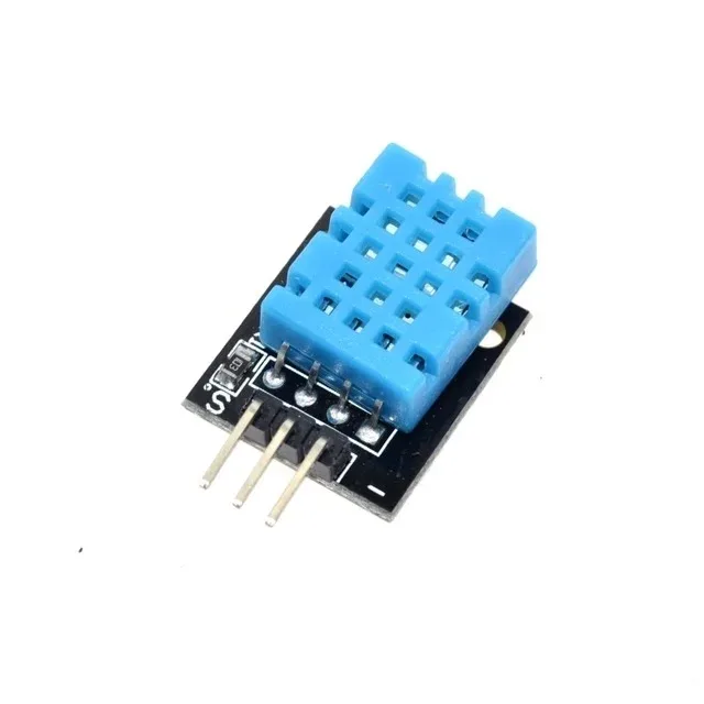
DHT11 Temperature and Humidity Sensor Module
Add a temperature and humidity readout to your ESP32 smart home panel. One GPIO pin, simple library, live sensor data displayed on your TFT screen.
Libraries Setup: TFT_eSPI and LVGL
For ESP32 + TFT display projects, the TFT_eSPI library by Bodmer is superior to Adafruit GFX in both speed and features. Combined with LVGL (Light and Versatile Graphics Library), you get a professional-grade UI framework with buttons, labels, sliders, charts, and animations.
Install via Arduino Library Manager:
- TFT_eSPI by Bodmer
- lvgl by lvgl (install version 8.x for best compatibility with available tutorials)
- XPT2046_Touchscreen by Paul Stoffregen (for resistive touch)
After installing TFT_eSPI, configure it for ILI9341 by editing User_Setup.h in the TFT_eSPI library folder:
// In User_Setup.h
#define ILI9341_DRIVER
#define TFT_CS   15
#define TFT_DC    2
#define TFT_RST   4
#define TFT_MOSI 23
#define TFT_SCLK 18
#define TFT_MISO 19
#define TOUCH_CS 21
#define SPI_FREQUENCY  40000000
#define SPI_TOUCH_FREQUENCY  2500000
For LVGL, copy the lv_conf_template.h from the LVGL library to your Arduino libraries folder root, rename it lv_conf.h, and set #define LV_COLOR_DEPTH 16 and #define LV_HOR_RES_MAX 320 and #define LV_VER_RES_MAX 240.
Designing the Touch UI with LVGL
LVGL provides a widget-based UI system where you create screens, add widgets (buttons, labels, switches, sliders), and attach event callbacks. Here is a minimal smart home panel UI with four toggle switches:
#include <TFT_eSPI.h>
#include <lvgl.h>

TFT_eSPI tft = TFT_eSPI();
static lv_disp_draw_buf_t draw_buf;
static lv_color_t buf[320 * 10];

lv_obj_t *sw[4];
const char* labels[] = {"Lights", "Fan", "AC", "Geyser"};
int relay_pins[] = {25, 26, 32, 33};

void my_disp_flush(lv_disp_drv_t *disp, const lv_area_t *area, lv_color_t *color_p) {
  uint32_t w = area->x2 - area->x1 + 1;
  uint32_t h = area->y2 - area->y1 + 1;
  tft.startWrite();
  tft.setAddrWindow(area->x1, area->y1, w, h);
  tft.pushColors((uint16_t *)&color_p->full, w * h, true);
  tft.endWrite();
  lv_disp_flush_ready(disp);
}

void switch_event_cb(lv_event_t *e) {
  lv_obj_t *target = lv_event_get_target(e);
  for (int i = 0; i < 4; i++) {
    if (target == sw[i]) {
      bool state = lv_obj_has_state(sw[i], LV_STATE_CHECKED);
      digitalWrite(relay_pins[i], state ? LOW : HIGH); // active LOW relay
    }
  }
}

void create_panel() {
  lv_obj_t *scr = lv_scr_act();
  lv_obj_set_style_bg_color(scr, lv_color_hex(0x1a1a2e), LV_PART_MAIN);

  lv_obj_t *title = lv_label_create(scr);
  lv_label_set_text(title, "Smart Home Panel");
  lv_obj_set_style_text_color(title, lv_color_hex(0xff6b00), LV_PART_MAIN);
  lv_obj_align(title, LV_ALIGN_TOP_MID, 0, 10);

  for (int i = 0; i < 4; i++) {
    lv_obj_t *lbl = lv_label_create(scr);
    lv_label_set_text(lbl, labels[i]);
    lv_obj_set_style_text_color(lbl, lv_color_white(), LV_PART_MAIN);
    lv_obj_set_pos(lbl, 20, 50 + i * 45);

    sw[i] = lv_switch_create(scr);
    lv_obj_set_pos(sw[i], 220, 45 + i * 45);
    lv_obj_add_event_cb(sw[i], switch_event_cb, LV_EVENT_VALUE_CHANGED, NULL);
  }
}

void setup() {
  for (int i = 0; i < 4; i++) {
    pinMode(relay_pins[i], OUTPUT);
    digitalWrite(relay_pins[i], HIGH); // relay off
  }
  tft.begin();
  tft.setRotation(1);
  lv_init();
  lv_disp_draw_buf_init(&draw_buf, buf, NULL, 320 * 10);
  static lv_disp_drv_t disp_drv;
  lv_disp_drv_init(&disp_drv);
  disp_drv.hor_res = 320; disp_drv.ver_res = 240;
  disp_drv.flush_cb = my_disp_flush;
  disp_drv.draw_buf = &draw_buf;
  lv_disp_drv_register(&disp_drv);
  create_panel();
}

void loop() {
  lv_timer_handler();
  delay(5);
}
LM35 Temperature Sensors
Display real-time room temperature on your ESP32 smart home panel. Analog output connects to ESP32 ADC — simple and reliable for temperature monitoring.
Adding MQTT and WiFi Control
MQTT makes the smart home panel truly smart by allowing remote control from a phone app, voice assistant, or automation scripts. Install the PubSubClient library in Arduino IDE. Here is the WiFi and MQTT integration skeleton to add to your sketch:
#include <WiFi.h>
#include <PubSubClient.h>

const char* ssid = "YourWiFiName";
const char* password = "YourWiFiPassword";
const char* mqtt_server = "192.168.1.100"; // your Mosquitto broker IP

WiFiClient espClient;
PubSubClient mqttClient(espClient);

void mqttCallback(char* topic, byte* payload, unsigned int length) {
  String msg = "";
  for (int i = 0; i < length; i++) msg += (char)payload[i];

  // topic: home/panel/relay/0  payload: ON or OFF
  if (String(topic) == "home/panel/relay/0") {
    bool state = (msg == "ON");
    digitalWrite(relay_pins[0], state ? LOW : HIGH);
    if (state) lv_obj_add_state(sw[0], LV_STATE_CHECKED);
    else lv_obj_clear_state(sw[0], LV_STATE_CHECKED);
    lv_obj_invalidate(sw[0]);
  }
  // Repeat for other relays...
}

void connectMQTT() {
  while (!mqttClient.connected()) {
    if (mqttClient.connect("ESP32SmartPanel")) {
      mqttClient.subscribe("home/panel/relay/#");
    }
    delay(2000);
  }
}
Run Mosquitto MQTT broker on a Raspberry Pi or any always-on computer in your home network. Use the MQTT Dash or IoT MQTT Panel Android app to create buttons on your phone that send ON/OFF messages to the same topics. Now your wall panel and phone app stay in sync — toggling one updates the other in real time.
For Home Assistant integration, add MQTT switch entities in configuration.yaml pointing to the same topics. Your ESP32 panel will then appear as a native Home Assistant device controllable via Google Assistant or Alexa.
Integrating Relay Modules for Real Loads
Standard 5V relay modules use active-LOW logic: pulling the IN pin LOW activates the relay (closes the NO contact). The ESP32 GPIO outputs 3.3V HIGH by default, which is enough to trigger most relay module optocouplers — but verify your specific module supports 3.3V input trigger. Some modules have a jumper to disconnect the optocoupler isolation and connect directly to 5V, which does NOT work safely with ESP32’s 3.3V GPIOs.
For controlling Indian 230V/50Hz appliances (lights, fans, geysers), wire the relay NO (Normally Open) contact in series with the Phase wire of the appliance. Never switch the Neutral. Keep mains wiring inside the enclosure separated from the 3.3V/5V electronics using a physical separator plate. Use appropriately rated wire (minimum 1.5 sqmm for 10A loads).
For fans with speed control, use a relay to switch power and a separate TRIAC dimmer module for speed regulation. Do not attempt PWM speed control of induction fans via relay — it will damage both the relay and the motor.

BMP280 Barometric Pressure Sensor Module
Add barometric pressure and altitude to your ESP32 panel’s environment display. I2C keeps the SPI bus free for your TFT screen — perfect coexistence on ESP32.
Enclosure and Wall Mounting
A wall-mounted smart home panel needs a clean enclosure to be taken seriously. Options for Indian makers:
- 3D printed: Design a front bezel with a rectangular cutout for the display. Print in PETG (heat-resistant, better than PLA for wall-mounted electronics) at 20% infill. Many local 3D printing services in Indian cities charge Rs. 200-500 for a small enclosure.
- Modular electrical box: Standard 3-module Anchor/Legrand modular plate cutouts (86x86mm or 86x146mm) can be adapted to hold a 2.8-inch display. The electrical gang box mounts flush in the wall for a truly professional appearance.
- Acrylic laser cut: A dark acrylic front panel with a display cutout and finger-jointed sides is elegant and easy to source from local laser cutting shops for Rs. 300-600 including material.
For wiring power from the wall, use a Hi-Link HLK-PM01 (5V/600mA) or HLK-PM03 (3.3V/1A) mains-to-DC module hidden inside the gang box. These are compact, CE-marked, and widely used in Indian maker community builds. They convert 230V AC to 5V DC in a module smaller than a matchbox.

GY-BME280-3.3 Temperature, Humidity and Pressure Sensor
Display comprehensive room environmental data on your ESP32 smart home panel. Single I2C connection gives you three sensor readings for richer dashboard information.
Frequently Asked Questions
Q1: Which ESP32 board is best for a TFT touch smart home panel?
The standard 38-pin ESP32 DevKit V1 is the most widely available and documented option in India. For space-constrained builds, the ESP32-S3 with built-in USB-OTG is gaining popularity. Avoid the ESP8266 for this project — it lacks the processing power and SPI speed to run LVGL smoothly with a 2.8-inch display. The ESP32 runs LVGL at 30+ fps; the ESP8266 struggles at 5-10 fps.
Q2: Can I use capacitive touch instead of resistive for the smart home panel?
Yes. The GT911 and FT6236 are common capacitive touch controllers on 2.8-4.0 inch TFT modules. They communicate via I2C and provide much smoother touch experience than resistive XPT2046. However, capacitive touch modules in this size range cost Rs. 600-1200 in India vs Rs. 250-400 for resistive equivalents. For a wall panel used by multiple family members, the capacitive touch is worth the premium.
Q3: How many relays can I control from a single ESP32 without external power?
The ESP32 can source approximately 40mA per GPIO pin (maximum 1200mA total across all pins). A standard 5V relay module draws 70-80mA per relay from the 5V supply, which must come from the USB/VIN power, not the 3.3V GPIO. Four relay modules drawing 320mA total from 5V is safe with a 1A+ supply. Use a separate 5V power line for the relay coils — do not power them from the ESP32’s onboard 3.3V regulator.
Q4: How do I prevent relay chatter when ESP32 reboots or WiFi reconnects?
Set all relay GPIO pins as OUTPUT with initial HIGH state (relay off) in setup() before any other initialisation. Use ESP.restart() instead of hardware reset where possible to maintain GPIO state briefly during reboot. Store appliance states in NVS (non-volatile storage) using Preferences library and restore them on boot so the panel remembers the last state after a power cut.
Q5: Can the smart home panel work offline without internet or MQTT broker?
Absolutely. The local touch control works entirely independently of WiFi and MQTT. The relays are controlled directly via GPIO from the LVGL touch callbacks. MQTT is additive — it provides remote control and voice assistant integration, but removing the WiFi connection from the code leaves you with a fully functional local touchscreen panel that controls your relays just fine. This is actually a good design principle: local control always, remote control optional.
Build Your Smart Home Panel with Zbotic Components
Get all the sensors, displays, and modules for your ESP32 smart home project from Zbotic. Genuine components, fast shipping across India, and expert support for your build.


Add comment