
Adopting an ESP32 modular IoT project design philosophy transforms the way you build connected devices. Instead of writing the same Wi-Fi connection code, MQTT client setup, and sensor driver from scratch for every new project, a modular approach lets you snap together pre-tested building blocks. Whether you are a hobbyist in Chennai building your tenth home automation gadget or a startup in Pune prototyping an industrial sensor node, reusable project templates cut your development time by 60–70% and dramatically reduce bugs in production deployments.
Why Modular Design Matters for ESP32 Projects
The ESP32’s popularity in India has exploded over the last three years — and for good reason. At under ₹200 for a basic module, it offers dual-core 240 MHz processing, 520 KB SRAM, Wi-Fi, Bluetooth Classic and BLE, and a rich peripheral set. But as makers grow from blinking LEDs to deploying ten or twenty nodes in a real environment, the ad-hoc approach of copying and pasting code between projects becomes unsustainable.
Consider this scenario common among Indian IoT developers: you build a temperature monitoring system for your first floor, it works perfectly. Three months later you need to add sensors on the second floor and terrace. With a monolithic code approach, you copy the entire project, make changes in five places, and inevitably introduce bugs in the refactoring. Worse, when you find a critical bug in the Wi-Fi reconnection logic six months later, you must hunt down and patch every one of your deployed projects individually.
Modular design solves these problems by establishing a clear separation of concerns. Each module has a single responsibility, a well-defined interface (function signatures and callback types), and is independently testable. Your application code simply calls these modules without knowing their implementation details — the same way you use Arduino libraries today, except these are modules you own and control.
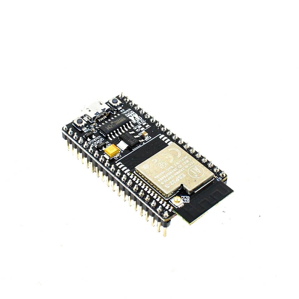
Ai Thinker NodeMCU-32S ESP32 Development Board – IPEX Version
The NodeMCU-32S is ideal for building and testing modular firmware templates — its full GPIO breakout and breadboard-compatible footprint make rapid prototyping effortless.
Recommended Project Directory Structure
A well-organised project structure is the foundation of modular development. For ESP-IDF (the official Espressif framework), use this directory layout:
my_iot_project/
├── main/
│   ├── app_main.c          # Entry point, ties modules together
│   ├── CMakeLists.txt
│   └── Kconfig.projbuild   # Project-specific menuconfig options
├── components/
│   ├── wifi_manager/       # Reusable Wi-Fi module
│   │   ├── include/wifi_manager.h
│   │   ├── wifi_manager.c
│   │   └── CMakeLists.txt
│   ├── mqtt_client/        # Reusable MQTT module
│   ├── sensor_drivers/     # Sensor abstraction layer
│   │   ├── dht_driver/
│   │   ├── bme280_driver/
│   │   └── ds18b20_driver/
│   ├── ota_updater/        # OTA firmware update module
│   ├── nvs_config/         # Configuration persistence
│   └── power_manager/      # Sleep modes and wake sources
├── test/                   # Unit tests
├── sdkconfig.defaults      # Default build configuration
└── CMakeLists.txt
For Arduino framework users, a similar structure works using PlatformIO. Create a lib/ directory at your project root and place each module as a separate subdirectory with its own library.json manifest. PlatformIO’s library manager treats these as local libraries, providing the same clean separation without leaving the Arduino IDE ecosystem.
Building Your Core Module Library
Start with these five essential modules that every ESP32 IoT project needs. Build them once, test them thoroughly, and reuse them forever.
1. Wi-Fi Manager Module
A robust Wi-Fi manager should handle connection, reconnection, and a provisioning fallback (AP mode with a captive portal for initial credentials entry). Key responsibilities:
- Connect using stored credentials from NVS on boot
- Monitor connection state and auto-reconnect with exponential backoff
- Provide a callback mechanism:
wifi_register_state_callback(fn)so other modules react to network changes - Start a SoftAP + HTTP provisioning server if no credentials are stored
2. MQTT Client Module
Wrap ESP-IDF’s mqtt_client or PubSubClient (Arduino) with a higher-level API:
mqtt_publish(topic, payload, qos)— with a queue for offline bufferingmqtt_subscribe(topic, callback)— register multiple callbacks per topic pattern- Automatic reconnection tied to the Wi-Fi manager’s state callback
- Last Will and Testament (LWT) setup at connection time for device availability tracking
3. Sensor Abstraction Layer
Define a common sensor interface struct that all driver implementations satisfy:
typedef struct {
    esp_err_t (*init)(void *config);
    esp_err_t (*read)(sensor_data_t *out);
    esp_err_t (*deinit)(void);
    const char *name;
} sensor_driver_t;
Application code uses sensor->read(&data) regardless of whether the underlying sensor is a DHT11, BME280, DS18B20, or any future sensor. Swapping hardware requires only changing the driver registration, not the application logic.
4. OTA Updater Module
Over-The-Air updates are non-negotiable for any production deployment in India where devices may be physically inaccessible. The module should:
- Check a version endpoint (your HTTPS server) on boot and at a configurable interval
- Compare firmware versions and download + apply only when a newer version is available
- Verify SHA256 signature before applying the update to prevent corrupted or malicious firmware
- Roll back automatically if the new firmware fails to boot three times (using ESP-IDF’s rollback mechanism)
5. Power Manager Module
For battery-powered nodes, the power manager coordinates sleep scheduling across all other modules:
- Deep sleep with RTC-preserved state for sensor data queues
- Wakeup source registration: timer, GPIO, touch, ULP co-processor
- Pre-sleep callback chain: MQTT flush → Wi-Fi disconnect → peripherals off → sleep
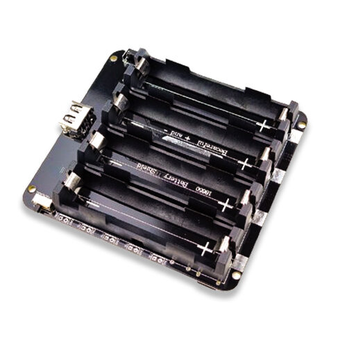
4 x 18650 Lithium Battery Shield V8 V9 for Arduino ESP32 ESP8266
Power your battery-operated ESP32 sensor nodes with this 4-cell shield — perfect for remote deployments where your power manager module will control deep sleep cycles.
Configuration System with NVS and JSON
Configuration management is where many ESP32 projects stumble. Hardcoding Wi-Fi credentials, MQTT broker addresses, and sensor thresholds in firmware means recompiling and reflashing for every configuration change — completely impractical for deployed devices. A proper configuration system stores all mutable settings in NVS (Non-Volatile Storage) and exposes them through a provisioning interface.
The recommended architecture uses a layered approach:
- Compile-time defaults: Kconfig (ESP-IDF) or
#defineconstants for factory defaults - NVS runtime storage: Overrides applied at provisioning time, persisted across reboots
- Remote configuration: MQTT topic
device/{id}/configcarries JSON updates that are applied and persisted to NVS immediately
The JSON configuration schema for a typical sensor node looks like this:
{
  "wifi_ssid": "MyHomeNetwork",
  "wifi_password": "secure_pass_here",
  "mqtt_broker": "192.168.1.100",
  "mqtt_port": 1883,
  "publish_interval_sec": 60,
  "deep_sleep_sec": 300,
  "alert_temp_high": 40.0,
  "alert_temp_low": 5.0
}
Testing and Validation Strategies
Unit testing firmware on embedded systems is undervalued in the Indian maker community. The ESP-IDF framework includes a unit test framework (unity) and supports running tests on both native hardware and on the host computer via CMake. For modular code, host-based testing is especially powerful:
- Mock hardware peripherals: Use function pointers and dependency injection to replace I2C/SPI reads with mock data during tests
- Test core logic on PC: Business logic modules (data processing, alert thresholds, JSON parsing) run identically on Linux/Windows as on ESP32 — compile and test on your laptop at full speed
- Hardware-in-the-loop (HIL) tests: Run automated tests that exercise real sensor reads, Wi-Fi connections, and MQTT publishes on actual hardware using a CI/CD pipeline (GitHub Actions + self-hosted runner on a Raspberry Pi)

30Pin ESP32 Expansion Board with Type-C USB and Micro USB Dual Interface
The perfect breakout board for building modular ESP32 prototypes — all 30 pins accessible, dual USB interfaces for easy programming and power.
Hardware Template PCB Design Tips
Modular software templates are only half the story. Pairing them with a standardised hardware template PCB accelerates your project pipeline further. Key principles for your ESP32 hardware template:
- Standardise power input: Accept both 5V USB-C and a screw terminal for 7–12V DC input with an onboard AMS1117-3.3 or more efficient LDO/buck converter. This single template works on USB power during development and DC supply in production
- Include reset and boot buttons: These are mandatory for programming — save yourself from bridging GPIO 0 to GND with a jumper every time
- Add a status LED: A single RGB LED (WS2812B works great) or three separate LEDs (power/Wi-Fi/error) makes firmware state instantly visible without a serial monitor
- Expose I2C and SPI headers: Grove connectors (4-pin JST) for I2C and a 6-pin header for SPI let you plug sensor modules without soldering, enabling rapid hardware iteration
- Include UART programming header: Even if you use USB-UART on the board, a 6-pin UART header with DTR/RTS for auto-reset lets you program remotely with a programmer cable
- TVS diode protection on GPIO lines: Especially important for India where voltage spikes from inductive loads (motors, relays, solenoids) on shared power rails are common
Frequently Asked Questions
Should I use ESP-IDF or Arduino framework for modular projects?
For serious production deployments, ESP-IDF is the better choice. It provides proper component management, FreeRTOS task isolation between modules, Kconfig for compile-time configuration, and the full ESP32 feature set (ESP32-S3 AI accelerator, IEEE 802.11 LR, etc.) without Arduino abstraction overhead. For learning, hobby projects, and rapid prototyping, Arduino with PlatformIO works excellently and the modular principles described here apply equally. PlatformIO’s library management is far superior to Arduino IDE’s and supports private local libraries cleanly.
How do I share modules across multiple projects without duplicating code?
The cleanest approach is to maintain a private Git repository of your component library (e.g., on Bitbucket or GitHub). Each project references this repo as a Git submodule or using PlatformIO’s lib_deps with a Git URL. When you fix a bug or add a feature in the library, all projects get the update on their next git pull --recurse-submodules. Semantic versioning (v1.2.3) lets projects pin to specific tested versions while still being able to upgrade on demand.
What is the best RTOS task structure for a modular ESP32 project?
A clean task structure has one FreeRTOS task per module with a dedicated queue for inter-module communication. For example: Wi-Fi task (priority 5), MQTT task (priority 4), sensor reading task (priority 3), data processing task (priority 2), and a watchdog task (priority 6, highest) that monitors all others. Message queues between tasks replace global variables, making the system thread-safe by design. Keep stack sizes generous initially (4096–8192 bytes per task) and profile actual usage with uxTaskGetStackHighWaterMark() before optimising.
How do I version control hardware and firmware together for a modular project?
Use a mono-repository structure with separate directories for firmware, hardware (KiCad/EasyEDA files), and documentation. Tag releases with a combined hardware/firmware version (e.g., hw1.2-fw2.5.1) so you always know exactly which firmware version is compatible with which PCB revision. Store the hardware version in NVS at production flashing time so the firmware can adapt its behaviour based on detected hardware revision — useful when fixing hardware bugs between PCB spins.
Start Building Modular ESP32 Projects Today
Find all the ESP32 modules, expansion boards, and sensors you need to build your reusable IoT template library at Zbotic — shipped fast across India.


Add comment