
ESP32 GPIO Expander: PCF8574 Add 16 Digital Pins via I2C
Running out of GPIO pins is one of the most common frustrations when building complex ESP32 projects. Imagine connecting a 4×4 keypad, multiple relay modules, status LEDs, and a display all at once — the ESP32’s available GPIOs run out quickly. The solution is a dedicated ESP32 GPIO expander using the PCF8574 over I2C. This 8-bit I/O expander communicates over just two wires (SDA and SCL), and by chaining two PCF8574 modules you instantly gain 16 extra digital pins without consuming any additional GPIO. In this complete tutorial, we cover wiring, addressing, the Arduino PCF8574 library, and real project code.
Why You Need a GPIO Expander
The ESP32 has 38 pins in total, but many are restricted: GPIO 6–11 are connected to internal flash and cannot be used freely, GPIO 34–39 are input-only, and GPIO 0, 2, 12, and 15 have boot-mode constraints. After connecting SPI (4 pins), I2C (2 pins), UART (2 pins), and a few control signals, you may have fewer than 15 freely usable GPIOs.
A PCF8574 I2C GPIO expander solves this elegantly. It requires only the SDA and SCL lines already in use by other I2C peripherals (like an OLED display), so the net cost is zero additional ESP32 pins per expander. You can chain up to eight PCF8574 modules on a single I2C bus, theoretically adding 64 digital I/O pins using two wires.
PCF8574 Module Overview
The PCF8574 is an 8-bit quasi-bidirectional I/O port expander manufactured by Texas Instruments and NXP. Each of the 8 I/O pins (P0–P7) can be independently set as input or output by writing to the device register. Key specifications:
- Interface: I2C (up to 400 kHz Fast mode)
- Supply voltage: 2.5V to 6V (3.3V for ESP32 use)
- I2C address range: 0x20–0x27 (PCF8574) or 0x38–0x3F (PCF8574A)
- Output drive: 25 mA sink, 1 mA source (use for driving relay INs, LEDs via transistor)
- Interrupt output pin (INT): goes LOW when any input pin changes — great for polling-free input reading
- Address pins A0, A1, A2: set by solder jumpers on the module, selecting 8 unique addresses
The PCF8574A variant has a different base address (0x38), allowing both PCF8574 and PCF8574A to coexist on the same bus — giving you a theoretical 16 expanders (128 pins) on one I2C bus.
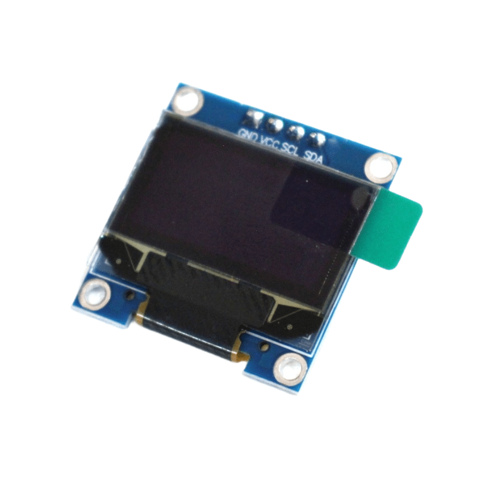
0.96 Inch I2C OLED Display – SSD1306 White
Share the same I2C bus with your PCF8574 expander. This SSD1306 OLED uses a different address (0x3C), so both devices coexist on just two GPIO pins.
Wiring PCF8574 to ESP32
The ESP32 defaults to GPIO 21 (SDA) and GPIO 22 (SCL) for I2C. If you have already initialised I2C for another device, simply connect the PCF8574 to the same bus lines.
| PCF8574 Pin | ESP32 Pin | Notes |
|---|---|---|
| VCC | 3V3 | Use 3.3V for ESP32 I2C compatibility |
| GND | GND | Common ground |
| SDA | GPIO 21 | Add 4.7kΩ pull-up to 3.3V if not present |
| SCL | GPIO 22 | Add 4.7kΩ pull-up to 3.3V if not present |
| INT | GPIO 4 (optional) | Interrupt on input change |
| A0, A1, A2 | GND/VCC | Set I2C address (000 = 0x20) |
Pull-up resistors: Most PCF8574 breakout modules include 10kΩ pull-ups on SDA and SCL. If using bare IC, add 4.7kΩ pull-ups from both lines to 3.3V. Too many devices on the bus with multiple pull-ups in parallel can create issues — use one 4.7kΩ set total.
I2C Addressing and Chaining
The three address pins A0, A1, A2 select one of 8 possible I2C addresses. On breakout modules, these are set via solder jumpers or header pins tied to VCC or GND:
| A2 | A1 | A0 | PCF8574 Address | PCF8574A Address |
|---|---|---|---|---|
| 0 | 0 | 0 | 0x20 | 0x38 |
| 0 | 0 | 1 | 0x21 | 0x39 |
| 0 | 1 | 0 | 0x22 | 0x3A |
| 1 | 1 | 1 | 0x27 | 0x3F |
To add 16 pins, use two PCF8574 modules with different address pin settings. Scan the I2C bus first with an I2C scanner sketch to confirm both modules are detected:
#include <Wire.h>
void setup() {
  Wire.begin(21, 22);
  Serial.begin(115200);
  for (byte addr = 1; addr < 127; addr++) {
    Wire.beginTransmission(addr);
    if (Wire.endTransmission() == 0)
      Serial.printf("Device found at 0x%02Xn", addr);
  }
}
Arduino Library Setup
Install the PCF8574 library by Renzo Mischianti from the Arduino Library Manager (search: PCF8574). This library supports both interrupt-based and polling input, individual pin control, and multiple instances for chaining.
Install via Arduino IDE: Sketch → Include Library → Manage Libraries → search PCF8574 → Install (Mischianti version).
Alternatively via Arduino CLI:
arduino-cli lib install "PCF8574 library"
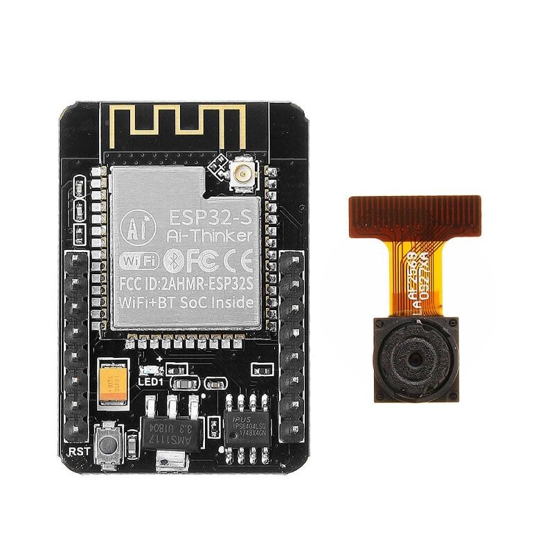
Ai Thinker ESP32 CAM – WiFi + Bluetooth Board
Combine the ESP32-CAM’s WiFi capability with PCF8574 GPIO expansion for IoT camera projects that also need multiple digital I/O channels.
Digital Input and Output Code
Here is a complete example using two PCF8574 modules to create 16 digital I/O lines:
#include <Wire.h>
#include <PCF8574.h>

// Two PCF8574 expanders: 0x20 and 0x21
PCF8574 exp1(0x20, 21, 22);  // SDA=21, SCL=22
PCF8574 exp2(0x21, 21, 22);

void setup() {
  Serial.begin(115200);

  // Expander 1: P0-P3 as outputs (relays), P4-P7 as inputs (buttons)
  exp1.begin();
  for (int i = 0; i < 4; i++) exp1.pinMode(i, OUTPUT);
  for (int i = 4; i < 8; i++) exp1.pinMode(i, INPUT);

  // Expander 2: All 8 pins as outputs (LEDs)
  exp2.begin();
  for (int i = 0; i < 8; i++) exp2.pinMode(i, OUTPUT);

  // Test: turn all LEDs on for 500ms
  for (int i = 0; i < 8; i++) exp2.digitalWrite(i, HIGH);
  delay(500);
  for (int i = 0; i < 8; i++) exp2.digitalWrite(i, LOW);
}

void loop() {
  // Read buttons from expander 1 (P4-P7)
  for (int btn = 4; btn < 8; btn++) {
    if (exp1.digitalRead(btn) == LOW) { // Active LOW (pull-up)
      int relay = btn - 4;
      // Toggle corresponding relay on expander 1 (P0-P3)
      bool state = !exp1.digitalRead(relay);
      exp1.digitalWrite(relay, state);
      // Mirror to LED on expander 2
      exp2.digitalWrite(relay, state);
      Serial.printf("Relay %d toggled: %sn", relay, state ? "ON" : "OFF");
      delay(300); // debounce
    }
  }
}
This sketch shows the power of chaining: 4 relay outputs + 4 button inputs on expander 1, and 8 LED outputs on expander 2 — all using just GPIO 21 and GPIO 22 on the ESP32.
Project: 4×4 Keypad + LCD with PCF8574
A very popular Indian maker project is a PIN-code door lock using a 4×4 matrix keypad and 16×2 LCD — both controlled through a single PCF8574 expander. The LCD uses the LiquidCrystal_I2C library (which itself uses a PCF8574 as a backpack), and the keypad rows/columns are wired to the second expander.
Bill of Materials:
- ESP32 DevKit
- PCF8574 module (address 0x20) — for keypad rows and columns
- 16×2 LCD with PCF8574 I2C backpack (usually 0x27)
- 4×4 membrane keypad
- Relay module (door lock solenoid control)
The keypad scanning logic scans one row at a time (pull LOW) and reads column states — all through PCF8574 reads/writes. With interrupt support via the INT pin connected to ESP32 GPIO4, you only scan the keypad when a key is actually pressed, saving CPU cycles for WiFi tasks.
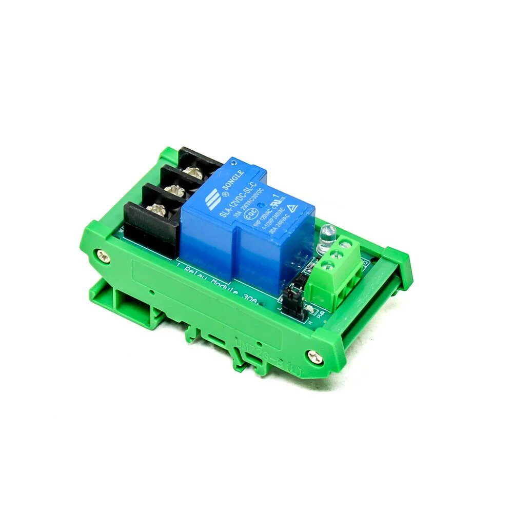
1 Channel 12V 30A Relay Module with Optocoupler
Control a door lock solenoid or electric bolt via PCF8574 output and this robust 30A relay with optical isolation — safe for controlling 12V security hardware.
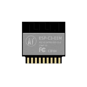
Ai Thinker ESP32-C3-01M Wi-Fi + BLE Module
A compact ESP32-C3 module with WiFi and BLE 5.0. Its single I2C bus pairs perfectly with PCF8574 expanders for IoT projects requiring many digital I/O lines.
Frequently Asked Questions
Can PCF8574 be used for analog inputs?
No. The PCF8574 is a digital-only GPIO expander. For analog expansion, use the ADS1115 (4-channel 16-bit ADC over I2C) or MCP3208 (8-channel 12-bit ADC via SPI) alongside the PCF8574.
How fast can PCF8574 switch outputs?
PCF8574 supports I2C at up to 400 kHz (Fast mode). Each write transaction takes roughly 40–50 microseconds at 400 kHz, limiting toggle frequency to about 10–20 kHz. This is fast enough for relays, LEDs, and buzzers but not for high-speed PWM.
Can I use PCF8574 with ESP8266?
Yes. The wiring is the same — use GPIO 4 (SDA) and GPIO 5 (SCL) on ESP8266. The PCF8574 library works with both ESP32 and ESP8266 Arduino cores without modification.
What is the difference between PCF8574 and MCP23017?
The MCP23017 offers 16 I/O pins in a single IC (vs PCF8574’s 8), has configurable pull-ups on each pin, and supports both I2C and SPI. It is the better choice if you need 16 pins from a single chip. PCF8574 is cheaper and simpler for 8-pin expansion needs.
Why does my PCF8574 not appear on I2C scan?
Check: (1) Pull-up resistors on SDA/SCL (4.7kΩ to 3.3V), (2) VCC connected to 3.3V not 5V when using ESP32, (3) address pins A0–A2 properly tied to GND or VCC. Run the I2C scanner sketch at 100 kHz first before trying 400 kHz.


Add comment