
A motorized camera slider turns any smartphone or DSLR footage into cinematic video — smooth, repeatable pulls that are impossible to achieve by hand. Commercial motorized sliders cost ₹15,000–₹80,000. Building your own with a stepper motor and Arduino costs under ₹3,000 and teaches you motion control fundamentals along the way.
This complete project guide walks you through every step: selecting the right stepper motor, wiring the driver, writing the Arduino firmware, and building the mechanical chassis. By the end, you’ll have a fully functional motorized slider capable of timelapse moves, realtime video pulls, and programmable multi-point motion sequences.
Project Overview & What You’ll Build
A camera slider consists of a rail (aluminium extrusion or dedicated slider rail), a carriage (the platform that holds your camera and rolls along the rail), and a drive system (motor + mechanism that moves the carriage). The motorized version adds:
- A stepper motor (for precise, repeatable position control)
- A stepper driver (to amplify the Arduino’s digital signals into motor current)
- An Arduino (the brain — controls speed, direction, and mode)
- A user interface (buttons and/or a potentiometer for speed adjustment)
- A power supply (7.4V–12V LiPo or 12V regulated supply)
What Modes Will It Support?
- Continuous realtime pull: Motor runs at constant speed — for video b-roll
- Timelapse mode: Motor moves a set distance per interval — for sunrise/sunset timelapses
- Shoot-move-shoot: Stop — trigger camera shutter — advance — repeat (requires shutter cable)
- Pendulum/back-and-forth: Moves to end, reverses — hands-free oscillating motion
Components List & Approximate Cost
| Component | Specification | Approx. Cost (₹) |
|---|---|---|
| NEMA 17 Stepper Motor | 42HS48, 1.2–1.7A, 4–6 kg·cm | 350–600 |
| A4988 Stepper Driver | 1/16 microstepping, 2A max | 60–100 |
| Arduino Uno / Nano | ATmega328P, 5V | 300–500 |
| GT2 Timing Belt (1m) | 2mm pitch, 6mm wide | 80–120 |
| GT2 Pulley (20T) | 5mm bore, 20 teeth | 60–100 |
| Aluminium Slider Rail | 60cm or 1m, with carriage | 600–1200 |
| Idler Pulley | GT2, 20T, 5mm bore | 40–80 |
| Potentiometer (10kΩ) | Speed control knob | 20–40 |
| Limit switches (×2) | End-of-travel protection | 30–60 |
| 12V 2A Power Supply | DC barrel jack | 150–250 |
| 100µF capacitor | A4988 power decoupling | 5–10 |
| Total Estimate | ₹1,700–₹3,060 |
Choosing the Right Stepper Motor
For a camera slider, the stepper motor needs enough torque to move the carriage + camera smoothly without stalling, but small enough to fit on the slider end without making it top-heavy.
Why NEMA 17?
NEMA 17 (42mm frame) is the sweet spot:
- Holding torque: 4–6 kg·cm — more than enough for a 1–1.5 kg camera load on a belt drive
- Standard size — fits readily available motor mounts designed for 3D printers
- Drives easily with A4988 or DRV8825 — no need for larger TB6600 driver
- 5mm D-shaft — compatible with GT2 pulleys and flexible couplings
Key Specs to Check
- Holding torque ≥ 4 kg·cm: Ensures smooth motion with 1kg camera at 1/16 microstepping (where torque is ~12% of holding torque = ~0.5 kg·cm — still adequate for belt drive)
- Current ≤ 1.5A/phase: Stays within A4988 limits (2A max, thermally derated to ~1.5A without heatsink)
- Step angle 1.8°: 200 full steps per revolution; with 1/16 microstepping and GT2 20T pulley = 0.00625 mm/step — ultra-smooth motion

42HS48-1204A NEMA17 5.6 kg-cm Stepper Motor — D-Type Shaft
The ideal spec for a camera slider: 5.6 kg·cm holding torque, 1.2A per phase, D-shaft for secure pulley mounting, and detachable cable for clean slider wiring. Ships across India.
Drive Mechanism: Belt vs Leadscrew
Two mechanical options for translating motor rotation to carriage movement:
GT2 Timing Belt Drive (Recommended)
- Fast — the carriage can move 30–100 mm/s without issue
- Lightweight — belt adds minimal weight to the slider
- Low noise at slow speeds
- Not self-locking — carriage can be pushed by hand when motor is off (useful for manual positioning)
- No backlash if belt is properly tensioned
- Linear travel per motor revolution = pulley circumference = π × 20T × 2mm pitch = 40π ≈ 125.7mm
T8 Leadscrew Drive
- Slower but higher torque multiplication
- Self-locking (carriage holds position without motor energised)
- Heavier, more complex to mount
- Good for heavy cameras or very slow timelapse at fractions of mm/hour
- More susceptible to Z-wobble-style smooth motion issues at slow speeds
For most camera slider projects, the GT2 belt drive is preferred. Use the leadscrew only if you need to park the camera at an angle without motor power, or if the camera load exceeds 2 kg.
Wiring: Stepper + A4988 + Arduino
A4988 Connections:
  VMOT → 12V supply (+)
  GND (motor) → 12V supply (-)
  VDD → 5V (Arduino 5V pin)
  GND (logic) → Arduino GND
  STEP → Arduino D3
  DIR → Arduino D4
  ENABLE → Arduino D5 (LOW = enabled)
  MS1 → Arduino D8 (or tie HIGH for fixed 1/16)
  MS2 → Arduino D9 (or tie HIGH for fixed 1/16)
  MS3 → Arduino D10 (or tie HIGH for fixed 1/16)
  RESET → SLEEP (bridged together)

Motor Connections (bipolar, 4-wire NEMA 17):
  1A, 1B → Coil A (check motor datasheet for colour pairs)
  2A, 2B → Coil B

100µF capacitor between VMOT and GND motor pins (close to A4988)

Potentiometer:
  Outer pins → 5V and GND
  Wiper → Arduino A0

Limit Switches:
  Left switch → Arduino D6 + GND (INPUT_PULLUP)
  Right switch → Arduino D7 + GND (INPUT_PULLUP)

Mode Button:
  Push button → Arduino D2 + GND (INPUT_PULLUP)
Setting A4988 Current Limit
This is critical. Over-current burns the driver; under-current causes missed steps. Formula: Vref = Imotor × 8 × Rsense. For most A4988 boards with 0.1Ω sense resistors: Vref = 1.2A × 8 × 0.1 = 0.96V. Measure Vref at the trimmer pot with a multimeter while the board is powered but not stepping. Adjust trimmer until you read 0.9–1.0V.
Arduino Firmware
#include <AccelStepper.h>

#define STEP_PIN 3
#define DIR_PIN  4
#define EN_PIN   5
#define POT_PIN  A0
#define BTN_PIN  2
#define LIMIT_L  6
#define LIMIT_R  7

AccelStepper stepper(AccelStepper::DRIVER, STEP_PIN, DIR_PIN);

bool timelapse = false;
unsigned long lastMove = 0;
int tlInterval = 5000;  // ms between timelapse steps
int tlSteps = 16;       // microsteps per interval

void setup() {
  pinMode(EN_PIN, OUTPUT);
  pinMode(BTN_PIN, INPUT_PULLUP);
  pinMode(LIMIT_L, INPUT_PULLUP);
  pinMode(LIMIT_R, INPUT_PULLUP);
  digitalWrite(EN_PIN, LOW);  // enable driver

  stepper.setMaxSpeed(3200);   // microsteps/sec
  stepper.setAcceleration(800);
}

void loop() {
  // Read speed from potentiometer
  int pot = analogRead(POT_PIN);
  int speed = map(pot, 0, 1023, 50, 3200);

  // Check limit switches
  if (digitalRead(LIMIT_L) == LOW && stepper.speed() < 0) {
    stepper.stop();
    return;
  }
  if (digitalRead(LIMIT_R) == LOW && stepper.speed() > 0) {
    stepper.stop();
    return;
  }

  // Mode toggle on button press
  static bool lastBtn = HIGH;
  bool btn = digitalRead(BTN_PIN);
  if (btn == LOW && lastBtn == HIGH) {
    timelapse = !timelapse;
    delay(200);  // debounce
  }
  lastBtn = btn;

  if (!timelapse) {
    // Continuous realtime mode
    stepper.setSpeed(speed);
    stepper.runSpeed();
  } else {
    // Timelapse mode: move tlSteps every tlInterval ms
    if (millis() - lastMove >= (unsigned long)tlInterval) {
      stepper.move(tlSteps);
      lastMove = millis();
    }
    stepper.run();
  }
}
Using AccelStepper Library
The AccelStepper library (install via Arduino IDE Library Manager: search “AccelStepper” by Mike McCauley) handles acceleration/deceleration profiles automatically. This is crucial for camera sliders — abrupt motor starts create visible vibration in the footage. The library’s setAcceleration() function creates smooth velocity ramp-up and ramp-down.
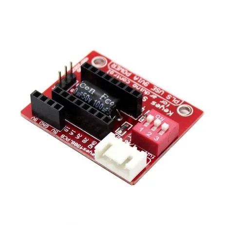
A4988 Stepper Motor Driver Controller Board
The go-to driver for NEMA 17 camera slider builds. Set current limit once with a screwdriver, plug into your Arduino shield or breadboard, and you’re running. Add the mandatory heatsink for continuous operation.
Timelapse Mode & Interval Shooting
For a timelapse of a sunrise (say 2 hours, 600mm slider travel), the math:
- Total duration: 7200 seconds
- Shooting interval: 5 seconds → 1440 frames
- Distance per frame: 600mm / 1440 = 0.417mm
- Microsteps per frame (GT2 belt, 20T pulley, 1/16 stepping): 0.417mm / (40π/3200 mm/step) = 0.417 / 0.039 ≈ 11 microsteps
Set tlSteps = 11 and tlInterval = 5000 in the firmware above. Connect your camera’s shutter via a 3.5mm cable (Arduino pin → 2.5kΩ → tip, sleeve to GND) and trigger before each move using digitalWrite.
Shoot-Move-Shoot with Shutter Trigger
#define SHUTTER_PIN 11

// In timelapse loop:
void shootMoveShoot() {
  // Trigger shutter
  digitalWrite(SHUTTER_PIN, HIGH);
  delay(100);  // half-press
  digitalWrite(SHUTTER_PIN, LOW);
  delay(100);
  digitalWrite(SHUTTER_PIN, HIGH);
  delay(200);  // full press / exposure
  digitalWrite(SHUTTER_PIN, LOW);
  delay(500);  // wait for camera write

  // Move carriage
  stepper.move(tlSteps);
  while (stepper.distanceToGo() != 0) {
    stepper.run();
  }
}
Mechanical Build Tips
Rail Options
- Dedicated slider kit: Pre-made aluminium slider rails with integrated bearings and carriage are available for ₹600–₹1,200 online. They include the carriage ball bearings and 1/4″ tripod thread. Easiest option.
- V-slot extrusion (2040): Use 20×40mm aluminium V-slot extrusion with V-wheel carriages (same as 3D printer X-axis). Extremely rigid and infinitely length-customizable. Mount motor at one end on a printed bracket, idler at the other.
- DIY from 15mm acrylic: Cheapest but lowest quality — not recommended for cameras above 500g.
Mounting the Motor
- Print or buy a NEMA 17 end-cap bracket that attaches to the slider rail ends
- Mount the GT2 pulley on the motor shaft — the D-shaft flat prevents the pulley set-screw from slipping
- Tension the belt via an idler pulley at the opposite end — use an eccentric nut or slotted idler mount for adjustment
- Clamp both ends of the belt to the carriage using printed belt clamps (Thingiverse has many designs)
Enclosure for Electronics
3D print a small box that clips onto the slider rail or sits on a separate accessory shoe. Include:
- Arduino Nano (smaller than Uno)
- A4988 mounted on a protoboard or mini CNC shield
- DC barrel jack input
- Mode button + speed potentiometer on the front face
- USB port accessible for firmware updates without opening box
Advanced Features & Upgrades
Pan Head Motor
Add a second stepper motor and A4988 to rotate the camera during the slide for a pan-tilt timelapse. Mount the pan motor on the carriage, driven by a small GT2 pulley geared for ~1° per motor step. Control both steppers synchronously from the same Arduino using two AccelStepper instances.
Bluetooth / WiFi Control
Replace the potentiometer interface with an HC-05 Bluetooth module or ESP8266 and control the slider from your phone. Libraries like BluetoothSerial (ESP32) or the Arduino BLE library make this straightforward. Set speed, direction, and mode from a simple Android app.
Multi-Axis Sync with Gimbal
Connect the slider Arduino to a gimbal controller (BaseCam SimpleBGC) via I2C or serial. Programme time-sync so the gimbal tilts as the slider travels — creating complex 3-axis moves that look like expensive crane shots.
OLED Display
Add a 128×64 OLED (I2C, SSD1306) to display current speed (mm/s), mode, position (in mm from home), and remaining travel. Essential for field use where you can’t have a laptop nearby.
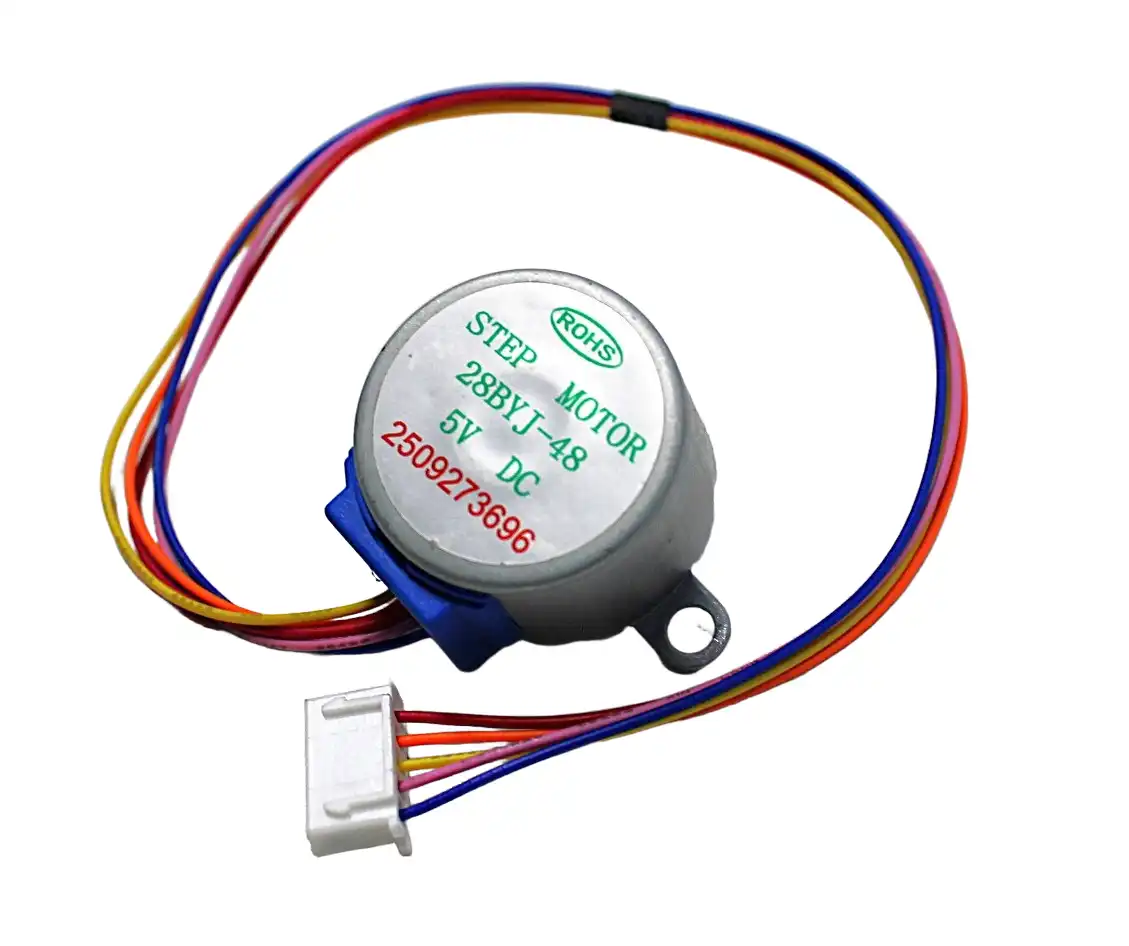
28BYJ-48 5V Stepper Motor
Budget option for learning stepper control — use this to prototype and test your slider firmware before investing in a NEMA 17. Great for pan head mechanism on lightweight phone sliders.

2805 140KV Gimbal Brushless Motor
For the pan/tilt head upgrade — this gimbal motor pairs with a SimpleBGC controller for ultra-smooth, silent pan movement during your camera slide. Low KV for high torque at low speed.
Frequently Asked Questions
How long can the slider travel in one go?
Slider length is limited by your rail length — typically 60cm, 80cm, or 1m for DIY builds. The motor and electronics have no inherent travel limit. For longer travel, use 2020/2040 V-slot extrusion which can be ordered in any length. Connect multiple sections with joining plates for 2m+ sliders.
Why is my footage vibrating/jittery at slow speeds?
This is stepper resonance — every motor has a resonant frequency range (often 300–600 RPM = 5–10 Hz) where vibration is worst. Solutions: (1) switch to a TMC2208 silent driver (stealthChop dramatically reduces resonance), (2) add a counterweight or damping foam pad under the electronics, (3) change speed slightly to exit the resonance band, (4) reduce microstepping from 1/16 to 1/8 (counter-intuitive, but changes resonance frequency).
Can I run this on batteries for outdoor use?
Yes. A 3S LiPo (11.1V nominal) or three 18650 cells in series (12.6V full charge) powers both the motor (via A4988 VMOT) and the Arduino (via its on-board regulator from the same 12V). Expect 3–6 hours of timelapse operation from a 2200mAh 3S pack. Add a LiPo protection board to prevent overdischarge damage.
Do I need limit switches?
Strongly recommended. Without limit switches, if the firmware or encoder loses track of carriage position (power interruption, missed steps), the carriage will ram the end of the slider and stall the motor. At slow timelapse speeds with a 1.2A motor, this could run for minutes before you notice, potentially damaging the belt anchor or carriage. Limit switches cost ₹15 each and add essential end-of-travel protection.
Can I use this slider with a smartphone instead of a DSLR?
Absolutely. Mount a phone holder (available for ₹100–200) on the carriage’s 1/4″ tripod thread. The electronics don’t know or care what camera weight they’re moving. With a smartphone (200g vs 1kg DSLR), you can use a lighter motor or run at lower current with even quieter motion.
What is the minimum speed achievable for ultra-slow timelapse?
With AccelStepper and 1/16 microstepping, the minimum stable speed is around 2–5 microsteps/second, or approximately 0.078–0.196 mm/minute on a GT2 belt drive. For even slower movement (1mm/hour), switch to timelapse shoot-move-shoot mode where the motor moves discrete steps and parks between them, rather than trying to creep at fractional microsteps/second.
Zbotic has everything you need in stock — NEMA 17 stepper motors, A4988 drivers, and motion accessories — all with same-day dispatch and fast shipping across India. Build professional-quality video tools for a fraction of the retail price. Browse stepper motors and drivers at Zbotic →


Add comment