
If you have ever noticed that your sensor readings become noisy when a motor starts up, or that your audio amplifier hums when you plug in a phone charger nearby, you have witnessed the effect of poor power supply rejection ratio (PSRR). PSRR is one of those specifications that beginners skip over in datasheets — but understanding it can be the difference between a circuit that works flawlessly and one that misbehaves in unpredictable ways. This guide explains PSRR from the ground up, covering what it means, why it matters, and how to improve it in your designs.
Table of Contents
- What is Power Supply Rejection Ratio (PSRR)?
- The Mathematics of PSRR
- PSRR in Op-Amps: Why It Matters
- PSRR in Voltage Regulators and LDOs
- How PSRR Varies with Frequency
- How to Improve PSRR in Your Circuits
- Practical Examples: Where PSRR Goes Wrong
- Frequently Asked Questions
What is Power Supply Rejection Ratio (PSRR)?
Power Supply Rejection Ratio (PSRR) is a measure of how well an electronic circuit or component can reject noise and variations on its power supply from appearing at its output. A high PSRR means the circuit is good at ignoring power supply noise. A low PSRR means the circuit will faithfully pass power supply ripple through to the output — which is almost never what you want.
PSRR appears in the specifications of op-amps, voltage regulators, LDOs (Low Dropout regulators), ADCs, DACs, and audio amplifiers. Anywhere the quality of your power supply affects the quality of your output signal or regulated voltage, PSRR is the relevant metric.
Think of PSRR as an attenuation factor: it tells you how much the circuit attenuates power supply noise before it reaches the output. A PSRR of 80 dB means a 1 mV ripple on the supply will appear as only 100 µV at the output (80 dB = factor of 10,000). A PSRR of 40 dB means that same 1 mV ripple appears as 10 mV at the output — 100 times worse.
The Mathematics of PSRR
PSRR is expressed in decibels (dB) and defined as:
PSRR (dB) = 20 × log₁₀ (ΔV_supply / ΔV_output)
Where ΔV_supply is the change in supply voltage (ripple or noise) and ΔV_output is the resulting change at the output due to that supply variation.
Some datasheets express PSRR as the inverse ratio (output change / supply change), so a high PSRR in dB is always better — but check the sign convention in each datasheet. A PSRR of 100 dB is excellent; 60 dB is decent; below 40 dB starts to become problematic for sensitive analog circuits.
Example: An LM358 op-amp has a typical PSRR of 100 dB at DC. This means a 1 V change in supply voltage would cause only a 10 µV change at the output — excellent rejection. However, at 10 kHz, this might drop to 60 dB (only 1000:1 attenuation), which is why PSRR must always be considered as a function of frequency, not just a single number.
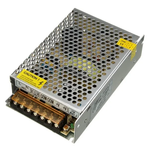
12V 10A SMPS – 120W DC Metal Power Supply
A robust 120W SMPS for powering your projects. Understanding PSRR helps you decide when to add extra filtering between this supply and your sensitive analog stages.
PSRR in Op-Amps: Why It Matters
In an ideal op-amp, the output depends only on the differential input voltage and the gain — not on what is happening on the supply pins. In reality, supply noise couples into the op-amp’s internal circuit through parasitic paths and affects the output. PSRR quantifies this coupling.
Op-amps have two PSRR specifications: one for the positive supply (PSRR+) and one for the negative supply (PSRR-). In dual-supply op-amps, both are relevant. In single-supply op-amps, PSRR+ is the critical number.
PSRR matters most in:
- Precision measurement circuits: Weighing scales, pH meters, strain gauge amplifiers. Supply noise appears as measurement error.
- Audio amplifiers: Supply ripple from a switched-mode supply or rectifier hum appears as audible noise at the output.
- Sensor signal conditioning: Amplifying small signals from thermocouples, pressure sensors, or photodiodes. Supply noise gets amplified along with the signal.
- Reference voltage generators: Op-amps used as unity-gain buffers for voltage references need high PSRR to maintain reference stability despite supply variations.
When selecting an op-amp for a noise-sensitive application, always look beyond the standard gain-bandwidth product and input offset voltage. Check PSRR versus frequency — some op-amps advertise 100 dB PSRR at DC but drop to 40 dB at just 1 kHz, making them unsuitable for audio or AC measurement applications.
PSRR in Voltage Regulators and LDOs
Voltage regulators and LDOs use PSRR to specify how well they attenuate input ripple before it reaches the regulated output. A 78xx linear regulator might have 60-70 dB PSRR at low frequencies. A well-designed LDO might achieve 70-80 dB.
This matters because even a regulated power supply has ripple. A 12V SMPS switching at 100 kHz will have some output ripple — typically 20-100 mV peak-to-peak. When you use this as the input to a 5V linear regulator, the PSRR of the regulator determines how much of that switching ripple appears on the 5V output.
With 60 dB PSRR: 50 mV input ripple → 50 µV output ripple (excellent).
With 20 dB PSRR: 50 mV input ripple → 5 mV output ripple (problematic for ADC references).
For sensitive analog circuits requiring a very clean supply, the common approach is to use a two-stage regulation: SMPS → large capacitor → LDO regulator. The SMPS handles efficiency; the LDO handles ripple rejection. The large capacitor between them helps the LDO by reducing the amplitude of ripple it needs to reject.
It is also worth noting that LDO PSRR drops dramatically at high frequencies (above 100 kHz). At the switching frequency of an SMPS, even a high-PSRR LDO may provide only 10-20 dB rejection. This is why proper input and output capacitors on the LDO are essential — the capacitors provide the bulk of high-frequency filtering that the LDO itself cannot.
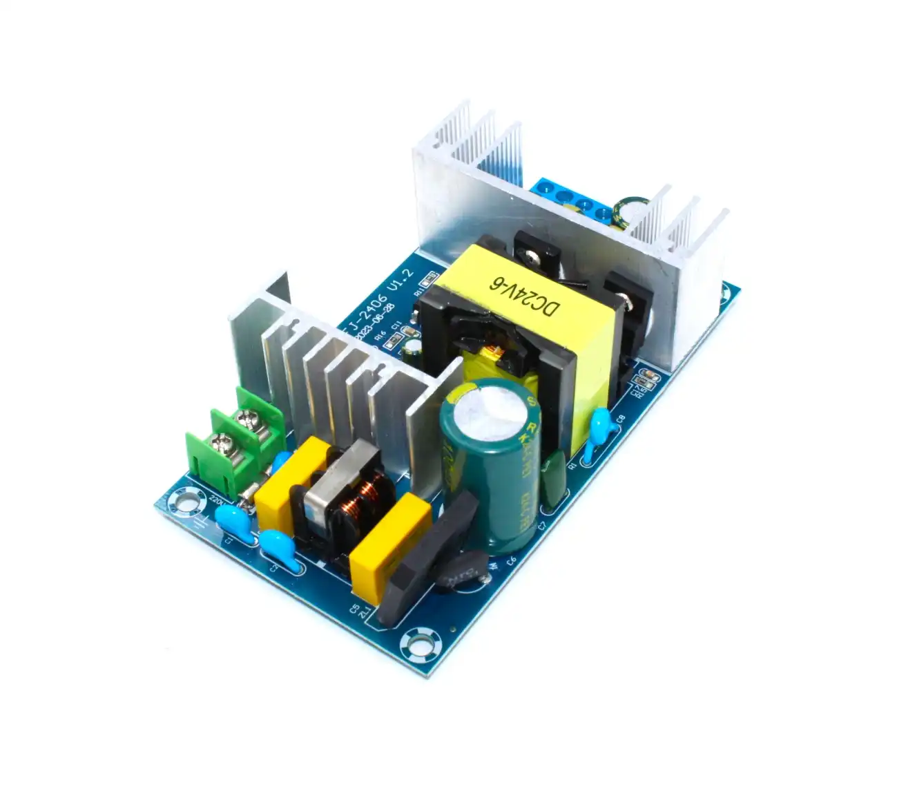
150W AC-DC Buck Converter 100V-240V to 24V Step Down Module
Efficient AC-DC conversion for bench power. When powering sensitive analog circuits downstream, add an LDO regulator after this module to leverage high PSRR filtering.
How PSRR Varies with Frequency
PSRR is not a single fixed value — it is a function of frequency. This is one of the most important and least understood aspects of the specification.
For op-amps, PSRR starts high at DC (often 80-120 dB) and decreases as frequency increases. This is because the internal compensation capacitors that give the op-amp its high open-loop gain at DC provide less impedance at high frequencies, allowing more supply noise to couple through. The PSRR rolls off at roughly the same rate as the open-loop gain: typically 20 dB per decade.
For LDO regulators, PSRR is also frequency-dependent. Most LDOs have excellent PSRR (60-80 dB) at DC and low frequencies, but the rejection degrades above the LDO’s bandwidth. At the SMPS switching frequency (usually 100 kHz to 2 MHz), LDO PSRR may have fallen to only 10-30 dB, making it nearly useless for high-frequency noise.
Practical implications:
- For audio circuits (20 Hz – 20 kHz), check PSRR at 1 kHz, not just DC.
- For SMPS post-filtering, check PSRR at the switching frequency of your SMPS.
- For RF circuits, PSRR at tens of MHz matters more than the DC value.
- Always look at the PSRR vs frequency graph in the datasheet, not just the headline number.
How to Improve PSRR in Your Circuits
There are several design techniques to improve effective PSRR regardless of the component specifications:
1. Bypass capacitors (decoupling)
Place ceramic capacitors as close as possible to every IC’s supply pin. Use both a small-value capacitor (100 nF ceramic for high-frequency bypass) and a larger bulk capacitor (10-100 µF electrolytic or tantalum for low-frequency energy reservoir). This is the single most impactful and lowest-cost technique for improving effective PSRR.
2. Use RC or LC filtering
A simple RC filter (series resistor + shunt capacitor to GND) provides additional supply noise filtering. The resistor value must be low enough to not create excessive voltage drop under load, but even a 1-10 Ω resistor with a 100 µF capacitor creates a useful low-pass filter with a cutoff around 160-1600 Hz.
3. Choose high-PSRR components
For sensitive analog stages, select op-amps and voltage references specifically for high PSRR. For example, the OPA2134 audio op-amp specifies 100 dB PSRR; the TL072 specifies only 80 dB — a meaningful 20 dB difference for audio applications.
4. Separate analog and digital supplies
Digital circuitry generates substantial supply noise through switching currents. Keeping analog and digital supply rails separate (with separate regulators or dedicated LC/RC filters) prevents digital noise from coupling into sensitive analog circuits.
5. Good PCB layout
Keep supply planes solid and unbroken under analog sections. Avoid routing high-current traces near sensitive analog signal paths. Use via stitching to ensure good ground plane continuity. Bypass capacitors should connect with the shortest possible traces between the supply pin, capacitor, and ground plane.

0.1µF 50V Capacitor (Pack of 50)
The workhorse of PSRR improvement: 100nF decoupling capacitors placed on every IC supply pin. This 50-piece pack ensures you have enough for any project.
Practical Examples: Where PSRR Goes Wrong
Example 1: Noisy temperature sensor readings
You are reading an LM35 temperature sensor through an Arduino’s ADC. The readings jump ±2°C whenever a relay clicks. The relay coil draws a surge of current from the supply, causing a voltage dip. This dip appears as a shift in the LM35’s output voltage (poor PSRR of the LM35 analogue section and Arduino ADC reference). Fix: add a 100 nF decoupling cap at the LM35 supply pin, add a 1-10 Ω resistor in series with the LM35 supply, and add a 100 µF bulk capacitor to the Arduino 5V rail. Separate the relay’s power from the sensor power if possible.
Example 2: Audio hum from SMPS
Your audio amplifier hums at 100 Hz (double the mains frequency) and produces a faint high-pitched whine at the SMPS switching frequency. The amplifier’s PSRR at 100 Hz and 100 kHz is insufficient to reject the SMPS output ripple. Fix: add a post-regulator LDO between SMPS and amplifier, add proper input/output decoupling on the LDO, and ensure the amplifier’s supply pins have bypass capacitors of multiple values (100 nF + 10 µF in parallel is a common combination).
Example 3: Buck converter noise on ADC reference
Your 12-bit ADC is powered from a 3.3V LDO which is in turn fed from a DC-DC buck converter. Despite using an LDO, ADC readings show noise correlated with the buck’s switching frequency. The LDO’s PSRR at the buck’s switching frequency (say 500 kHz) is only 15 dB — almost no rejection. Fix: add a ferrite bead + 10 µF capacitor between the buck output and LDO input, specifically chosen to attenuate the buck’s switching frequency.
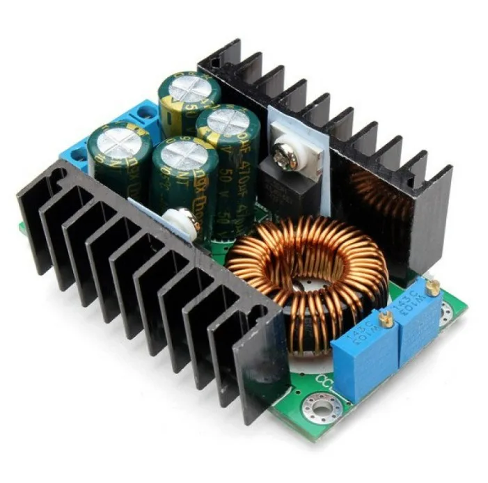
300W 10A DC-DC Step-down Buck Converter Adjustable Module
A high-power adjustable buck converter for your lab bench. When powering sensitive analog circuits, always add an LDO post-regulator to overcome the buck’s high-frequency ripple — PSRR in action.
Frequently Asked Questions
Is higher PSRR always better?
Yes, in virtually every practical situation. Higher PSRR means the circuit is better at rejecting supply noise. There is no downside to high PSRR. The only constraint is that achieving higher PSRR in a component typically requires more silicon area and design complexity, which increases cost.
How does PSRR relate to common-mode rejection ratio (CMRR)?
Both are rejection ratios that appear in op-amp datasheets. CMRR measures how well the op-amp rejects common-mode input signals (signals that appear equally on both input pins). PSRR measures how well it rejects supply noise. They are separate specifications measuring different rejection paths, but both are expressed in dB and higher is better in both cases.
Does adding decoupling capacitors improve PSRR?
Decoupling capacitors do not improve the PSRR of the component itself, but they reduce the amount of supply noise that the component needs to reject. If your supply has 50 mV ripple and decoupling capacitors reduce it to 1 mV at the supply pin of the IC, the effective noise at the output is 50x lower regardless of the component’s PSRR spec.
Why does PSRR matter more for ADCs than for digital logic?
Digital logic uses supply voltage only for switching threshold — as long as the supply stays within valid HIGH/LOW thresholds, the digital circuit works correctly. ADCs and DACs, however, convert analogue voltages that are referenced to the supply. Any noise on the supply directly appears as noise in the conversion result, limiting the effective resolution.
What is a typical PSRR value for a good LDO?
At DC and low frequencies (up to ~1 kHz), a good LDO achieves 60-80 dB PSRR. At 10 kHz, 50-70 dB. At 100 kHz, it may drop to 30-50 dB. At 1 MHz, 10-20 dB is common. Premium LDOs like the TPS7A47 are specifically designed for high-frequency PSRR and maintain 60+ dB even at 100 kHz.
—
Build cleaner, more reliable circuits with quality components from Zbotic! Whether you need bulk capacitors for decoupling, power supply modules, resistors, or sensors, Zbotic has everything for Indian hobbyists and engineers. Understanding PSRR transforms you from a hobbyist who wonders why circuits misbehave into an engineer who knows exactly how to fix them. Shop at Zbotic.in for fast delivery and quality-checked components across India.


Add comment